|
Fabrication & Part Modifications
With the design issues out of the way, part selection and fabrication issues needed to be addressed. I choose parts with the thought of fabrication ease and as few parts as necessary. One of the first things I found was that nearly all of the fittings needed trimmed so they fit flush together. I chucked many of the fittings in my Atlas Metal Lathe and trimmed off excess material. Another issue that needs addressed is gluing the fittings together. I advise using LOTS of PVC cement. We are talking gas tight connections here, so buy lots of PVC cement. Coat both pieces liberally, press together and wipe the excess cement away with a little lacquer thinner on a shop towel. The only gluing problem you are going to encounter will be with the 6" pieces. There is a lot of surface area that needs coated and a little applicator brush does not work well. I poured half of a small can of PCV glue into a small shallow bowl and applied it from there. You can roll the applicator head through the glue and right to the fitting. When connecting any thread type fittings, I would used a Teflon based sealer we are dealing with gas, not water pipe. I use PREMIER Teflon Pipe Sealant.
Sub-Assemblies
I broke the dryer down into three sub-assemblies. The upper assembly, the lower assembly and the channeling chamber. All are connected together with 4" PVC Pipe to form the final assembly. 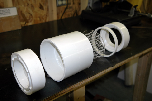 The only area that needs detailed explanation is the channeling chamber. To the left is an exploded view of the Channeling Chamber. You can click on the image for a larger view. The parts from left to right are: The only area that needs detailed explanation is the channeling chamber. To the left is an exploded view of the Channeling Chamber. You can click on the image for a larger view. The parts from left to right are:
(1) Bottom 4" x 6" Reducer
(2) 6" Coupler
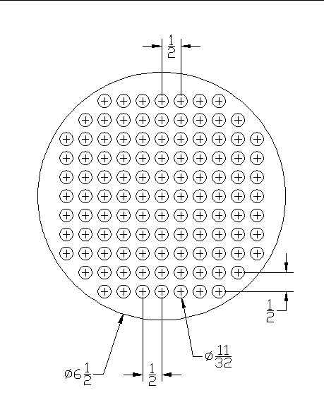
(3) Channeling Plate
(4) Spacer
(5) Top 4" x 6" Reducer.
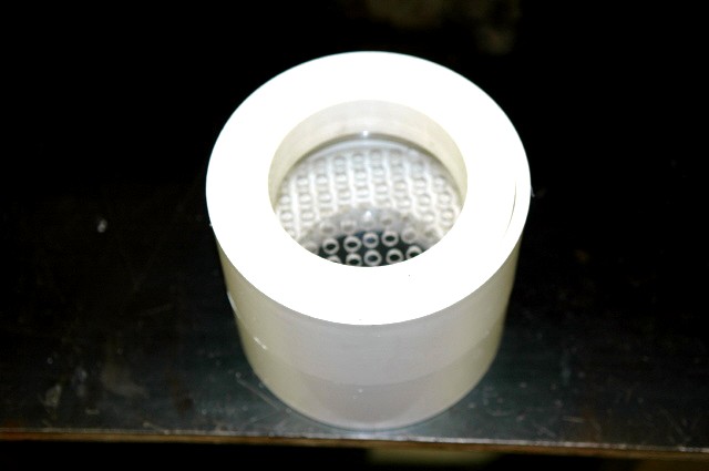
To make the channeling plate I traced the inside diameter of the coupling and cut out the circular shape in my band saw. I then made a template in AutoCAD and taped the paper template on the round plate. I then drilled a 3/32" pilot hole in the center of each circle. When complete, I remove the paper template and redrilled all the holes to their final size. I finished the job by deburring all of the holes. On the top reducer I cut 1/2" off the outside end, this will be the spacer. The spacers job is to create a open chamber area above the channeling plate. I then cut away the inner web and filed off the rough edges. At this point I dropped the channeling plate in the coupler, then the spacer and then the rest of the reducer. I measured how much of the reducer sticks above the coupler, marked it, then cut it so it will be flush with the top of the coupler. I then marked the other reducer and cut it to the same length. My reducers were hollow webbed, so I mixed up some bondo and filled the top web cavity up. I then took a belt sander to the top and smoothed it out. If you do not fill the top reducer web cavity, water will fill up and freeze and we know what that will do. When complete, assemble the coupling, channeling plate and spacer. Then glue the reducers into each end to form the channeling chamber assembly.
|