Harness #2, wires are lettered E,F,G & H |
Harness #1, wires are lettered A, B, C, & D. |

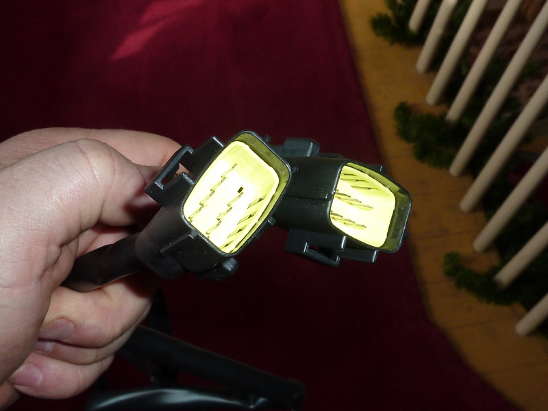
Here, both harness are shown |
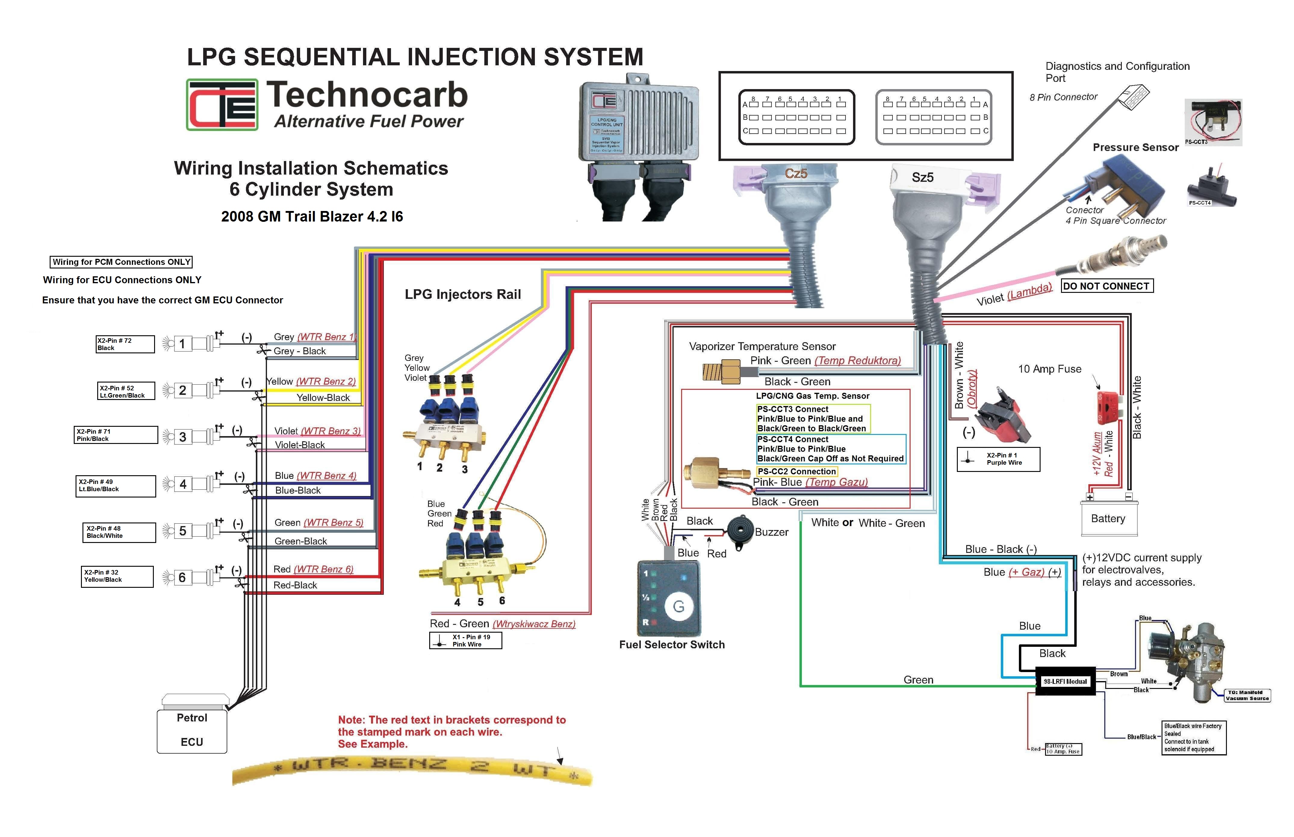
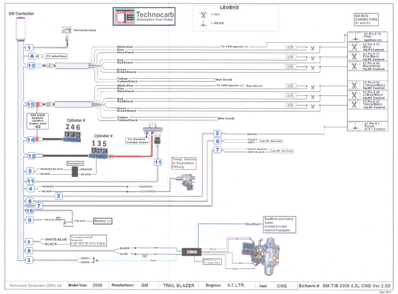
Wiring installation schematic |
Electrical wiring problems
(Click any pic for an enlarged view)
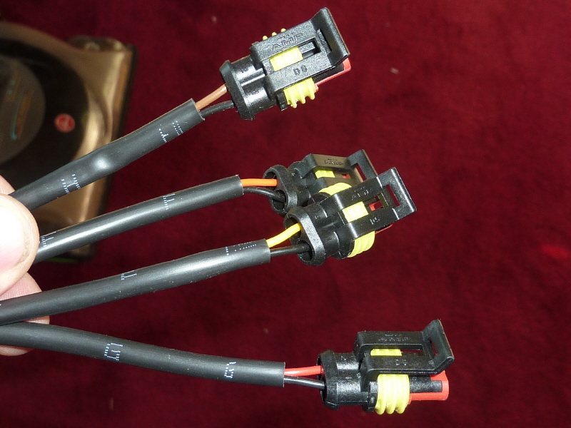
The CNG gas injector harness, #12 & #14, have 8 injector rail connectors, 4 per cable. The component connection schematic (CCS) shows nothing on how to wire the connectors. The Wiring installation schematic (WIS) shows 2 injector rails with 6 wires. However the wires shown are gray, Yellow, Violet, Blue, Green & Red. So when you look at the injector rail connector wires (shown below) they are Brown wire/Black wire, Yellow wire/Black wire, Red wire/Black wire and Orange wire/Black wire. What is needed? 1. An updated WIS showing the injector rail connectors (shown below) connected to the injector rail pictures (on the WIS) with color wires that match the existing cables. 2. Need the cylinder numbers on the injector rail pictures. 3. Show which of the 2 cables has the red band on the WIS and CCS. 4. Show which 2 of the 8 injector rail connectors are not used by their color wire.
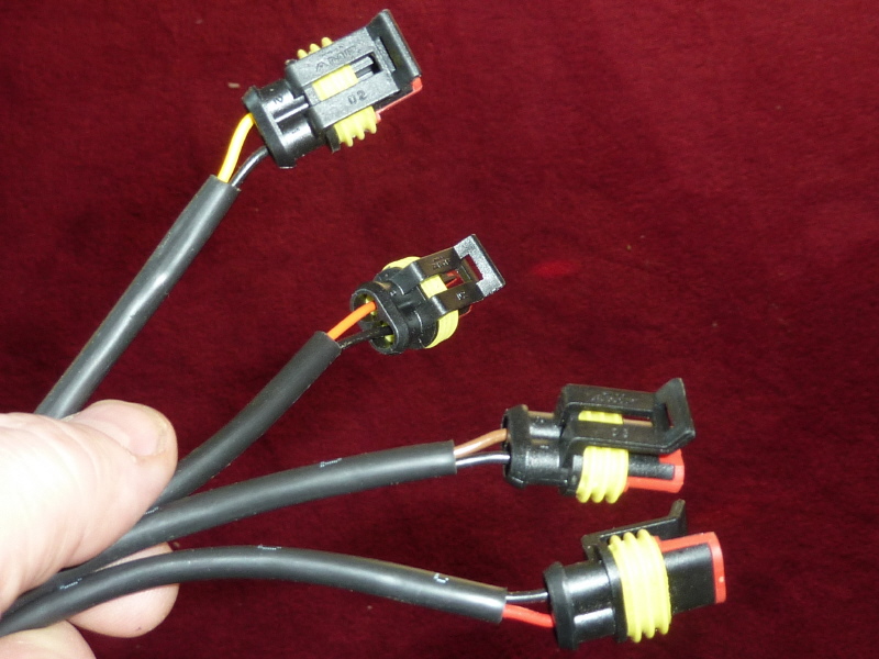
CNG Injector to Petro Injector Interface Harness #13 & #15. It will be extreamly diffucult to explain the problem because the WIS, CCS and existing harness wiring are all different and do not match. There are some aspects that are correct. What needs to happen is for the WIS & CCS to be updated to show the existing wiring harness (shown below) matching the schematis and diagrams. Here is what is correct:
1. On the WIS, the gasoline injector picture and GM wire colors are correct. The cylinder numbering also looks correct. However the pictured harness wire colors, of the WIS, do not match the existing wire harness (shown below).
2. On the CCS, the gasoline injector picture and GM wire colors are NOT correct. The cylinder numbering looks like V6 and not L6. The harness wiring color is also not correct when matched to the existing wire harness (shown below).
3. Show which of the 2 cables has the red band on the WIS and CCS.
4. Each of the Petro Injector Interface Harnesses have a lone red/white wire. Do each of these wires get connected together and then connected to the common pink wire that connects to each gasoline injector. If this is not correct, please show the correct wiring.
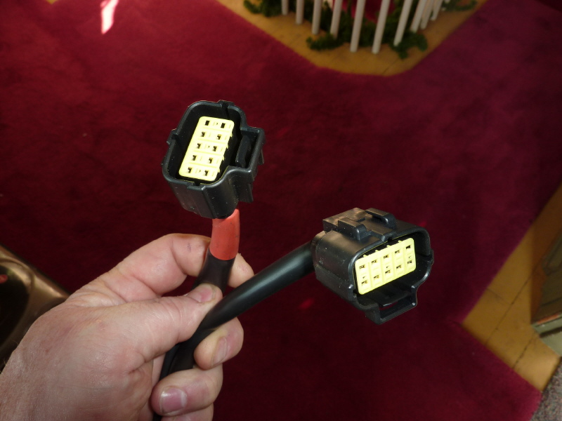
Here, both harness connectors are shown. |
Here are the matching connectors for the two wire extensions. |

Here, both harness extensions are shown. The wire colors are identical in both harnesses. Each harness has the following color wires: Gray/Gray-Black, Yellow/Yellow-Black, Violet/Violet-Black, Blue/Blue-Black, Green/Green-Black and Red/Red-Black. Each harness has an extra Red-White wire |
Component connection schematic |
General Questions
1. The main wiring harness shown on the WIS #X has a white-blue & black wires to be connected to a tank solenoid. The 98-LRFI fuel pressure interface also has a blue/black wire to be connected to a tank solenoid. Which one is correct?
2. The main wiring harness shown on the WIS #2 has a brown wire to be connected to a
2. On the WIS it shows a buzzer wired to the Fuel Selector Switch. My kit did not come with a buzzer. Does the Fuel Selector Switch have a built in buzzer? If not and I have to supply my own buzzer, can you provide the specs on the buzzer?