|
To start out I realized that in order to do this right I was going to have to really study the wiring diagrams. Then devise a plan and document what I was doing. This may be the first time in my life where I triple checked what I was doing. I fact when I was wiring the fuel injectors I lost count how many times I checked and re-checked what I was doing. I also photographed everything in case I needed to review something. |
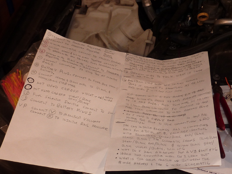
The first thing I did was to label every wire coming off the main wiring harness with a number. Then I wrote up a connection list stating what needed done wire by wire. |
With that the first order of business was to split the main wiring harness into wires running forward, backward and toward the engine. The first obstacle I ran into was a black cloth tape wrapped around the harness to support the wires. |
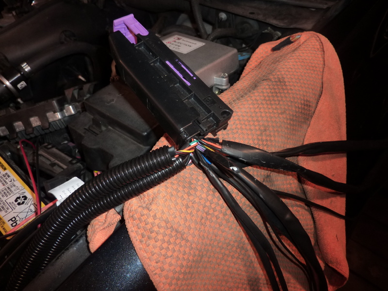
I cut the cloth tape away and began separating the wires. |
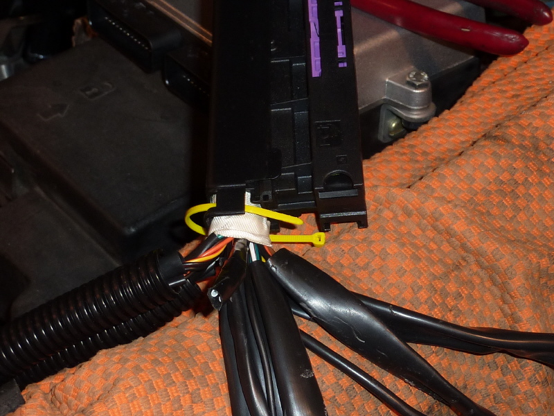
After separating the wires I removed the main plastic back connector support. I then re-wrapped the harness with 3M fiberglass cloth electrical tape and zip tied the support. |
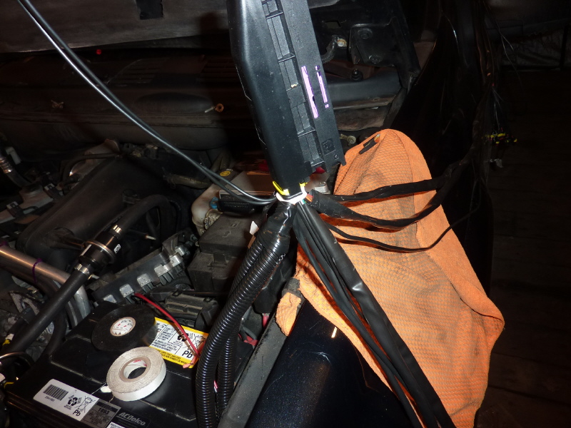
I then hung the connector so I could easily work on the cluster of wires. |
Here the cables are taking form into one of three sub harnesses. |

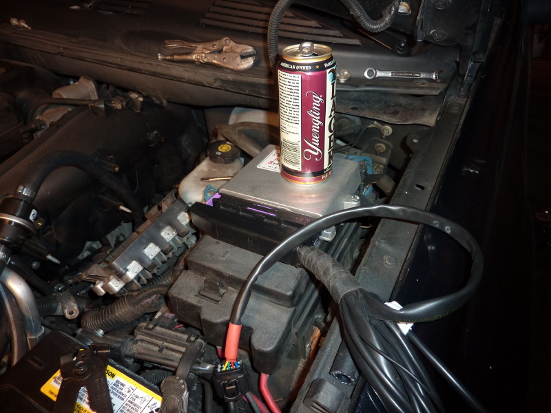
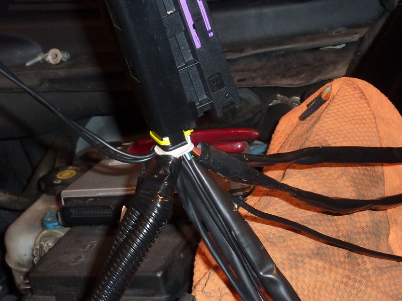
Once complete there are three sub harnesses to work with. The main harness was connected to the Technocarb ECM and the sub-harness were routed. |
The FGIM wiring harness runs forward in the engine compartment. Here plastic wire loom is being wrapped around the harness. The wire loom protects the wiring and makes the job look professional. |
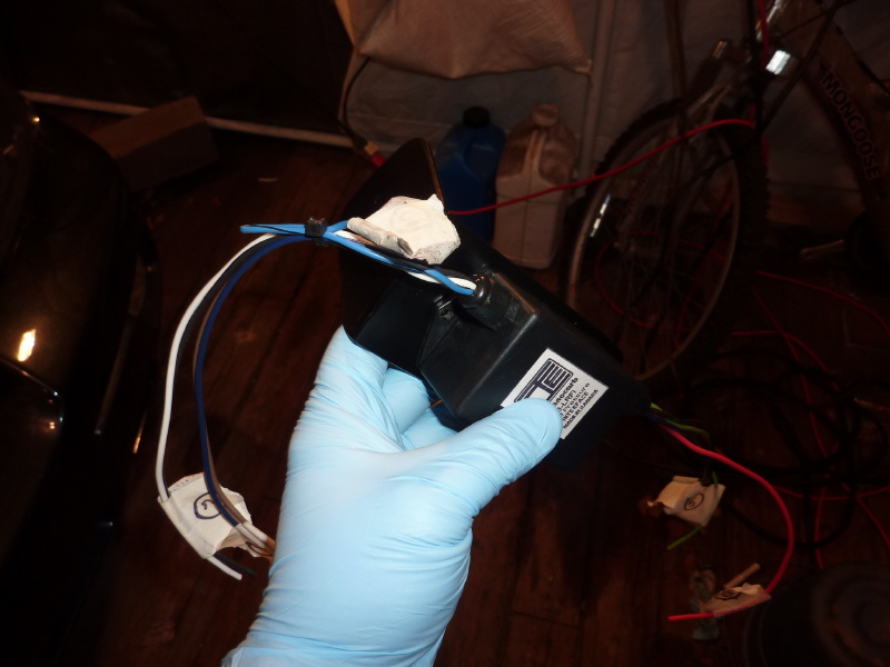
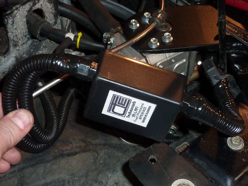
Here is the FGIM mounted on it's mount bracket. Notice the masking tape labels on the wire ends. They correspond to steps on my wiring list. |

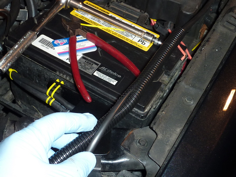
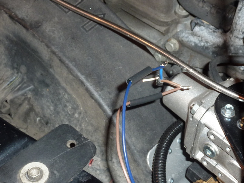
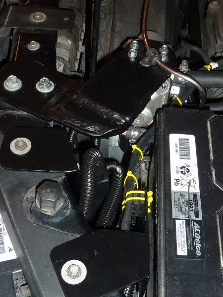
A 10A fuse is called for on the power feed of the FGIM. Here it is wired in line and the hot wire returns back to the battery in side the existing wire loom. |
After all the electrical connections are made I wrapped all the lose wires in electrical tape. |

On the other side of the FGIM the coolant temperature sensor gets connected. |
In this view main power for the CNG regulator is being wired in. |
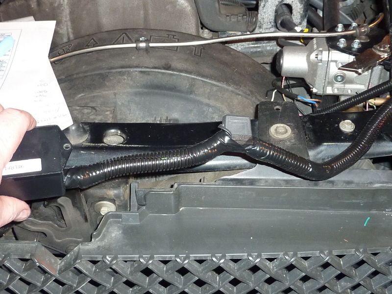
With all the connections made and loose wire wrapped in electrical tape. Black wire loom is slipped on all the wire bundles. |
Here the FGIM is ready to be dropped into place for mounting. |
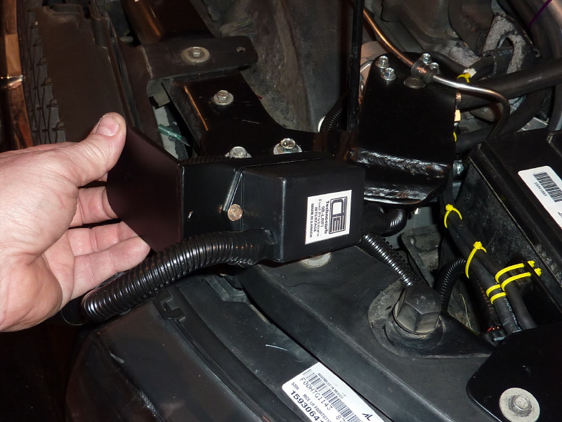
An installed view. |

Another installed view. |