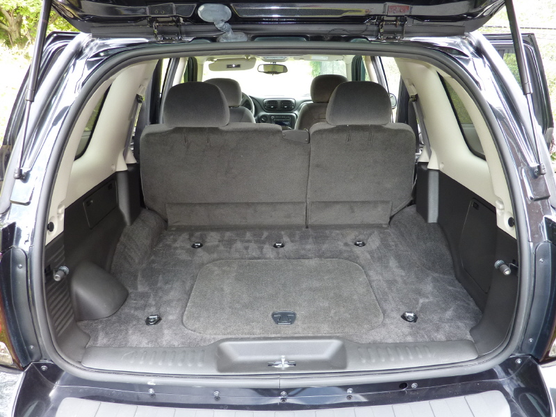
Now that the tank straps have been cut, it's time to layout the tank support and tank straps. Here is a pic of the rear of the Trailblazer. |
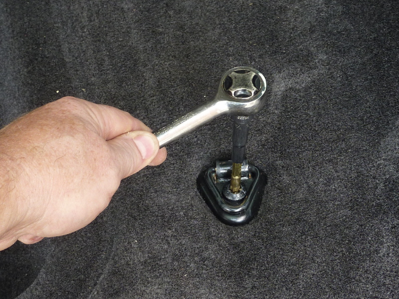
The Trailblazer has 5 tie downs that need removed. The fastener is a TorX type and has some type of thread locker on them. |
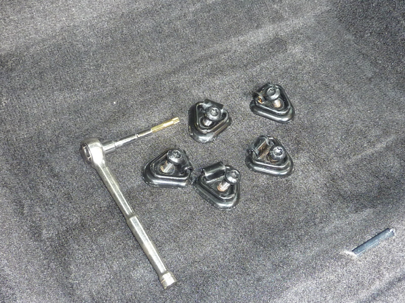
Here the tie downs have been removed. Keep them, the TorX bolts will come in handy later. If you want to use them. |

You will need to remove the rear trim piece. A flat screw driver is used to push against the clips. Do not pry up or it will break the clip. |
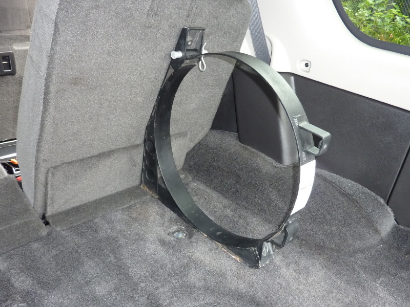
The important thing here is to check if the hatch compartment is big enough for both tanks. With the seat up, the tank strap fits the seat contour perfectly. Truly scarey. |

Here the faithful measurement is made and lucky for me there is 4" of clearance left at the hatch. |
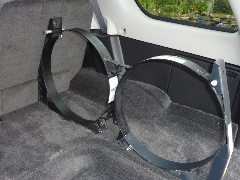
The second tank strap is added to make sure the top of the strap does not hit the hatch. |
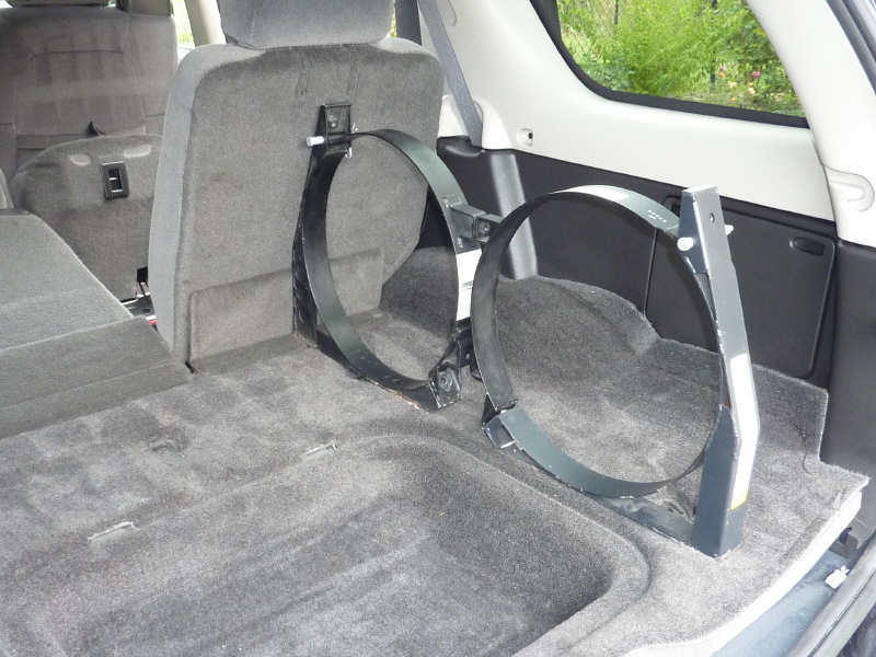
The hatch door angles in and there is plenty of clearance. I do not like the position of the straps and will probably position them angled back together. |
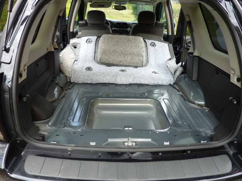
Here the carpet and foam pad is pulled up. It was nice to see that there was no obstructions to deal with. |
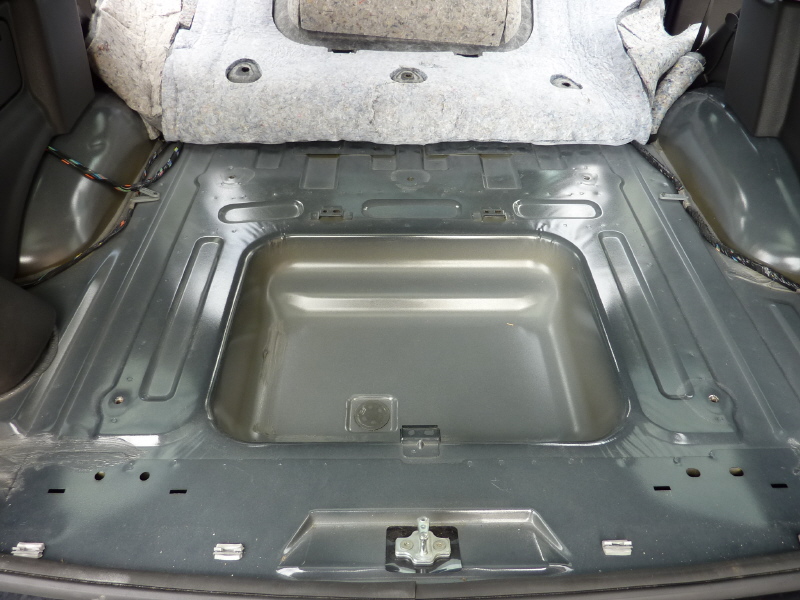
At this point I began taking measurements of the entire compartment. Every feature, hole and channel. These will be used to layout the tank bracket in AutoCAD. |
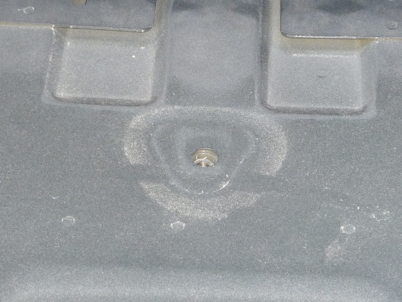
Here you can see the steel reinforcement plate outline on the sheet metal floor. This is important if you want to use this location as part of your bracket system.
|
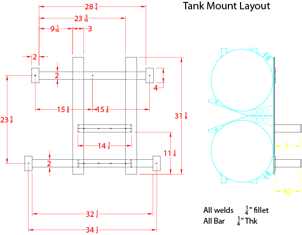
Here is the bracket system drawn up, to scale, with AutoCAD. The tank straps are shown to get the correct size for the main bars. |
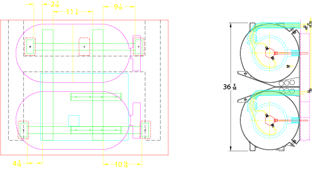
Here the under floor channels, tank positions, boots and hose layout are shown. To insure everything fits. |
|