|
I would like to start by saying that this was the toughest part of the whole conversion. It was truly beyond ugly. First of all everything is in the way, everything need relocated and Vaseline, crowbars and a shoe horn is needed to get the intake manifold out and back in again. The biggest obstacle your will run into is the rear intake manifold bolt. You can not see it and can barely feel it. You are completely blind. . . . . . Uggggg. |
I spent about 3 hrs. getting the bolt out and ended up buying 3 different sized 1/4" extensions and a 1/4" universal. You will also need a 1/4" 10mm socket and rachet. You will need to remove a rubber flap in the drivers fender well and reach in from there. I used masking tape to hold the socket, 1st extension, universal, 2nd extension and 3rd extension in a semi ridge shape just to get to the bolt location. It will be pot luck to hit it and when you do, it's miller time. Enough said! |
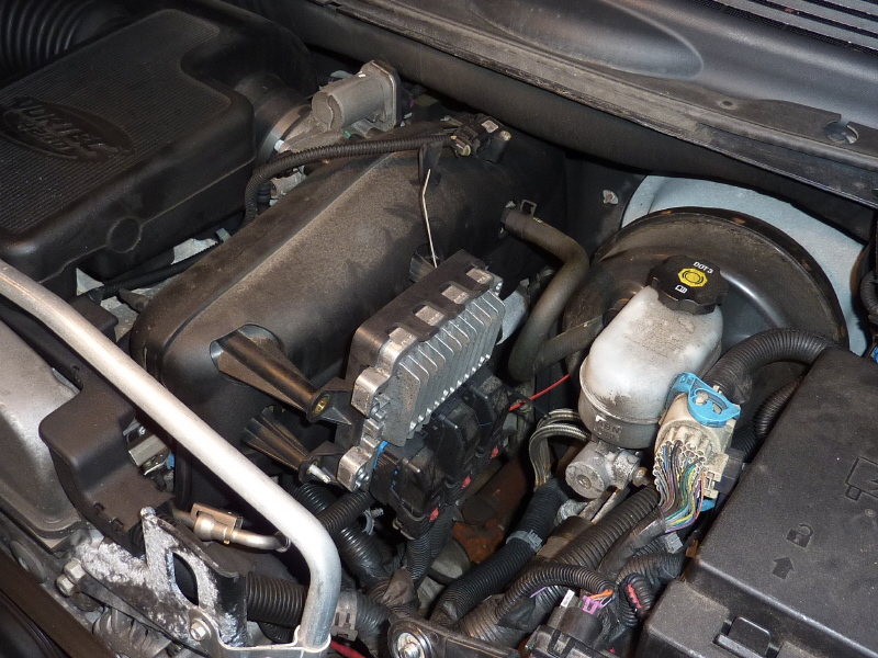
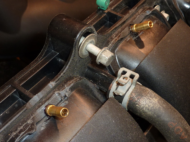
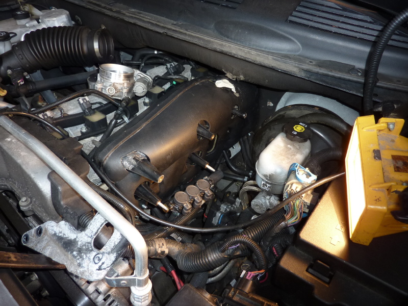
Here is what your are looking at. Big tip, I purchased an online subscription to online shop manuals. You will need the references. It indicated that to get the manifold out you needed to remove the serpentine belt and tensioner, the alternator and bracket and a few other brackets. I was not going there. |
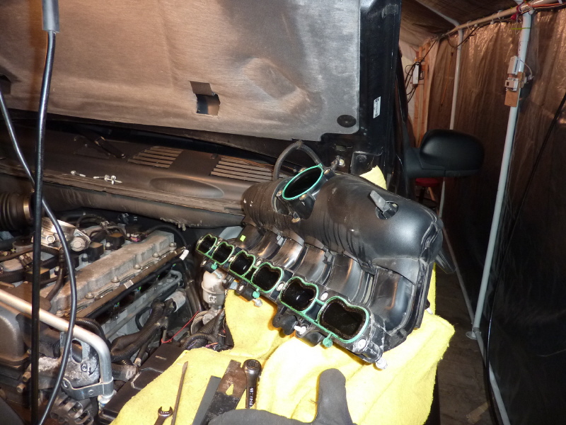
Here is the manifold out, finally. |
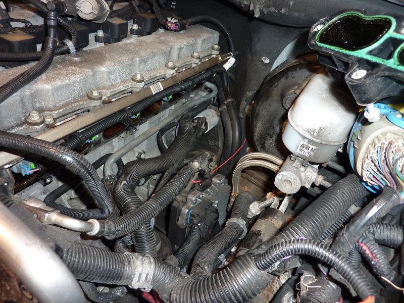
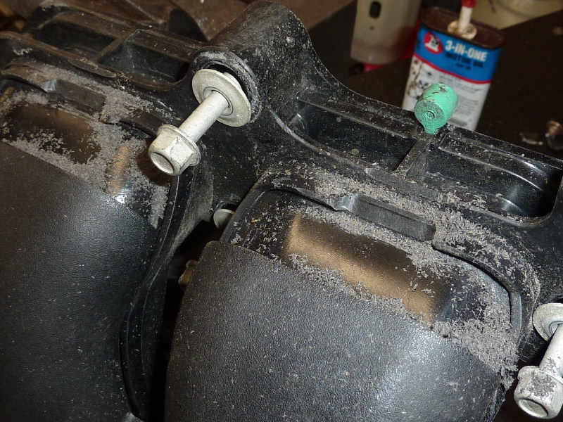
Once the manifold is out, you get a better view of all the wire loom that will need to be relocated for clearance of the injector rails. |
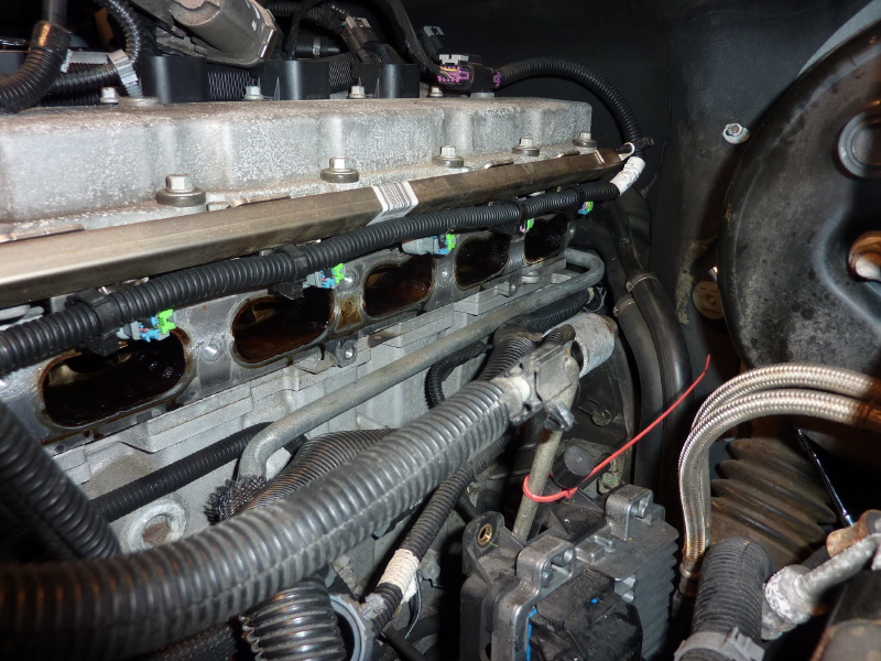
Also this view indicates that the existing gasoline injector rail is tucked into the inner arch area of the manifold. This forces the injectors to be mounted on the outside. |

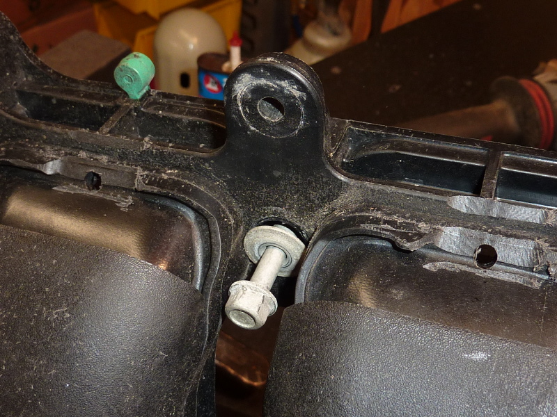
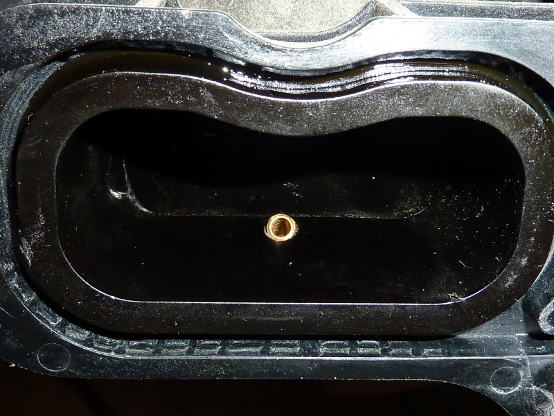
Here is the under side of one intake plenum. I made an angle jig to consistently grind the plastic casting away to get an angler flat area angled into the intake port. |
You want the angle to maximise the amount material for the injector threads. So spend some time and get it right. |
Once the grinding is complete you want to make or adjust your angle jig so you can drill consistent angled tap drill holes. You will need a 5mm or 15/64" tap drill to do the deed. |

Once all the drilling is complete, you will need a 6mm x 1 metric tap. Then tap out all the holes. Once done slightly chamfer the outside hole to match the taper on the injector. Then deburr the other side of the hole. |
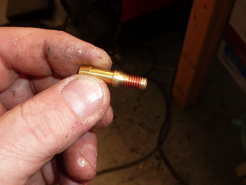
Here is an injector ready for insertion. Use a little red locktite on the threads. Lacquer thinner will clean up any mess.. |
Screw all the injectors in and snug them down. You do not have to tighten them as the locktite will insure they will never come out. |
Another shot half way across the manifold. |
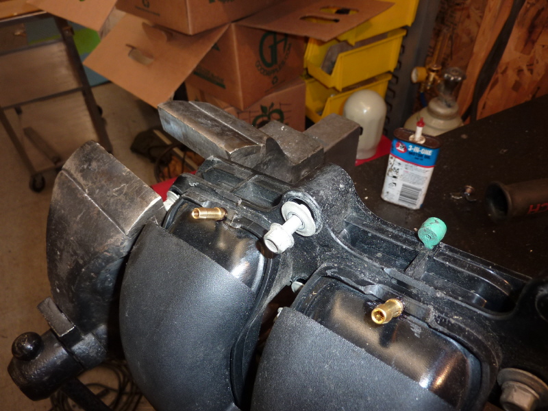
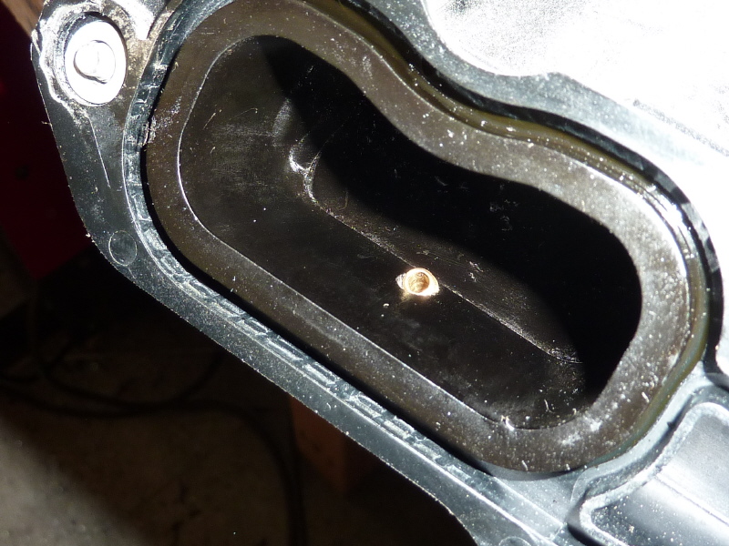
This is a view looking at the injector angle. Notice how it is angled to inject the natural gas stream into the inlet port. This is very important. |
Another angle for clarity. Once you are done, you will need to do a through cleaning. I use Black Magic Engine Shine. In my opinion it is far better than Gunk Engine Degreaser. Just put the manifold out in the sun and spray away. Let stand for 30 minutes. Use a pressure washer to clean and blow out all the holes and passages. |
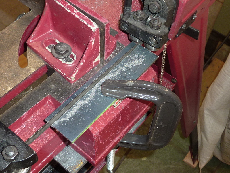
With the intake manifold done, it is time to build some injector rail brackets. Here I begin the process of sawing metal strips for the bracket. |
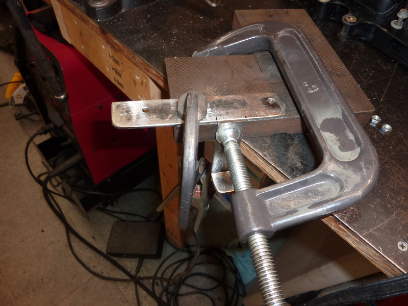
This is the front bracket clamped and ready for welding. There is a boss on the manifold flange that the welded piece connects to. |
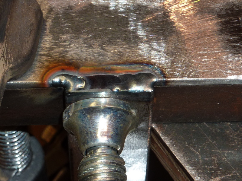
A view of the connector piece welded to the main support strip. |
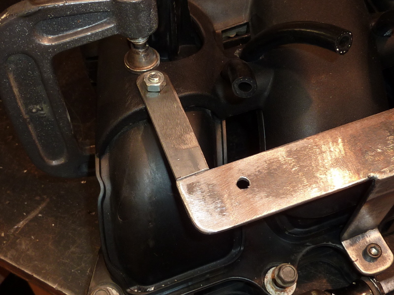
Here the bracket is attached and another connector piece is fitted. I TIG welded the piece while still attached to the plastic manifold. There is not a lot of heat produced, so if you are careful you can get away with this. |
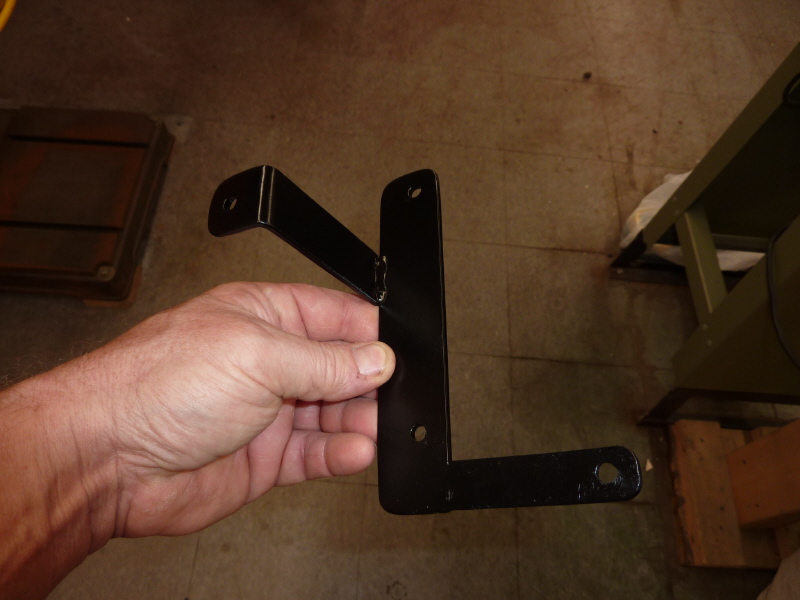
Front bracket complete, sanded and painted. |

Another view. |
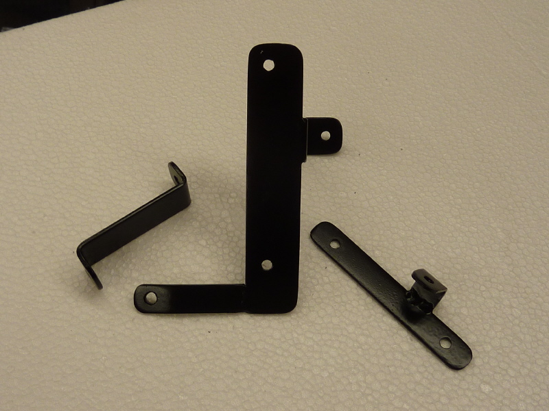
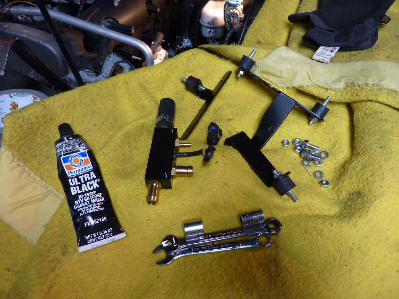
The rear bracket was far simpler to make. Shown is the front bracket, in the middle, flanked by the two piece rear brackets.. |
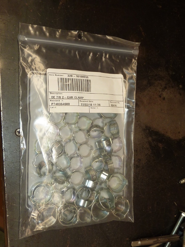
This is an assorted bag of Oetiker two eared clamps. I purchased them online. These are one time clamps, so if you mess up, you will need a new one. A special tool is needed to apply the clamp. Get it off Ebay. |
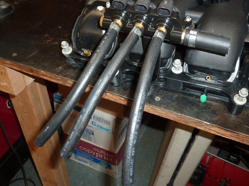
The front bracket is attached and the injector rail installed. The injector hoses need to be the same length. So I cut them to 12" and attached them. |
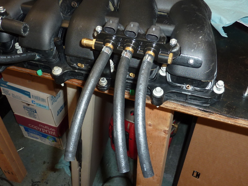
I then mounted the rear injector rail and injector hoses. |
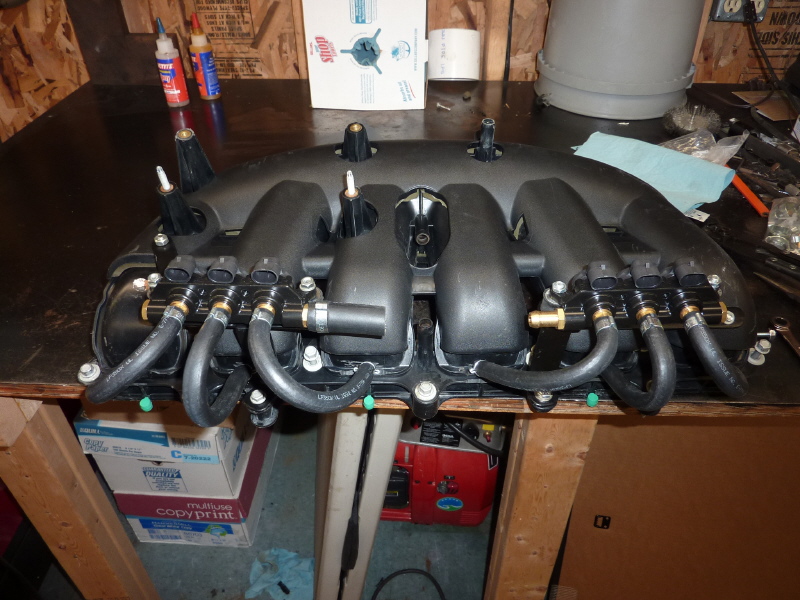
Once done I bent and measured each hose until I found a bend radius that satisfied every injector and gave me the absolute minimum length. I then then cut and clamped. |
Once complete the hose length was 7 1/4 ". Well with in the maximum allowed. |
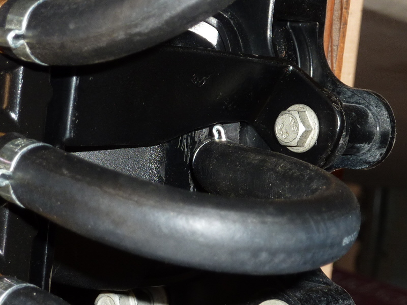
One thing I did find was I had to twist one of the front bracket legs and grind away a little metal for clearance of No. 2 injector hose. Opps. |

When I brought the manifold out to be reinstalled, I saw there was no way the manifold was going back in with the injector rails installed. |
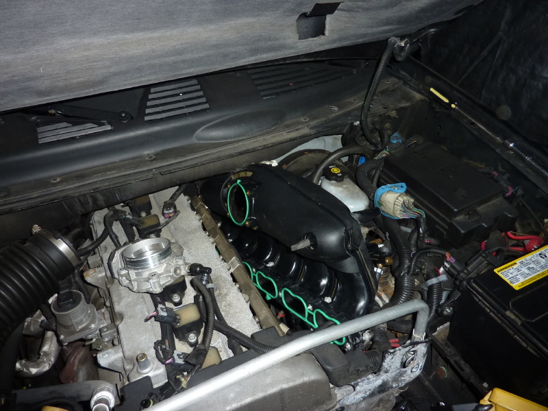
So I needed to remove the brackets and leave the injector rail hang free so they could be moved around. Here is the manifold going back in. |
It took time to jimmy the manifold in. I had to move wire loom around, wiggle and rock, pry and shove. In time I got it back in. I am not going to say anything about the curside manifold bolts, so there. |
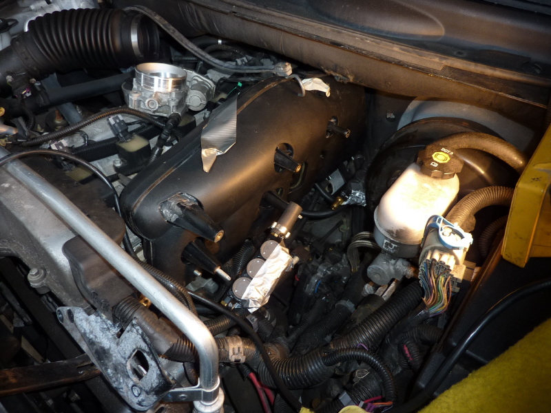
Here I am covering up the injector rails electrical connections, so crap does not fall into the connectors. |
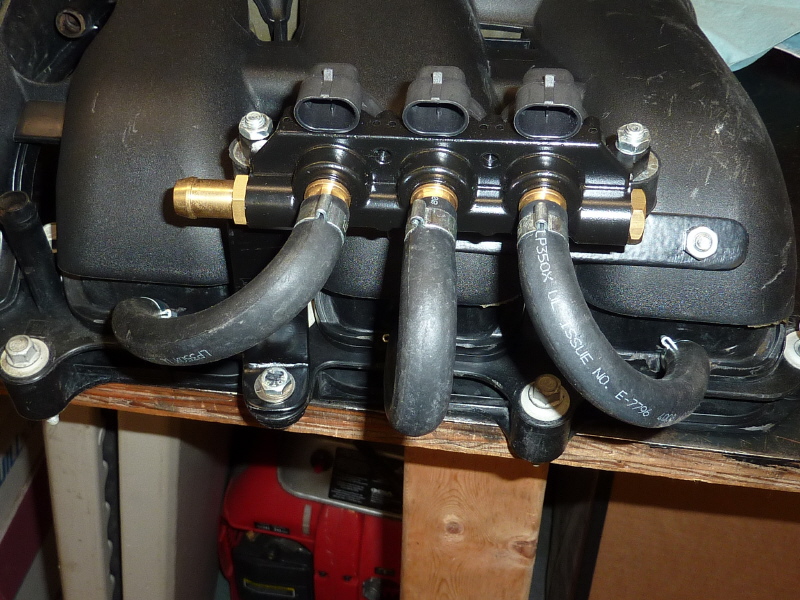
Now it is time to put the injector brackets on along with the gas supply tee and sensor. |
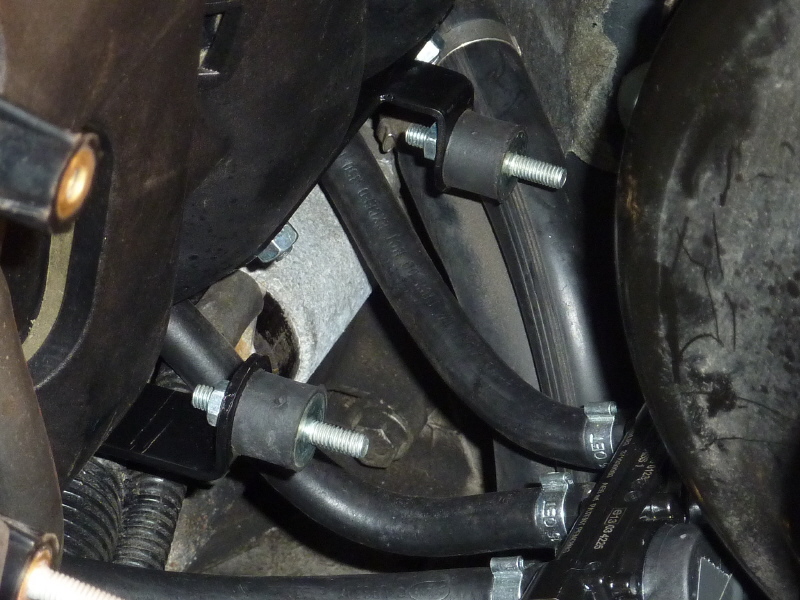
Here the rear brackets are installed. It is difficult getting under the manifold to tighten the bolts |
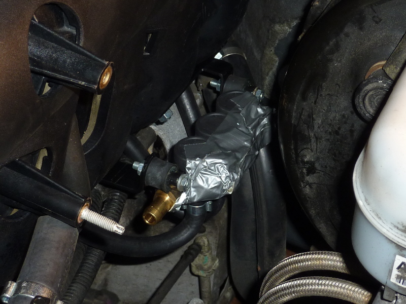
The rear injector rail is added. |
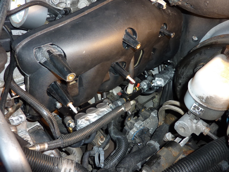
The front brackets and injector rails are installed in a similar fashion. |
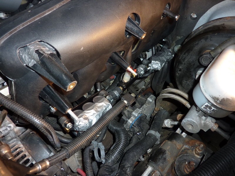
At this point the process of moving and re-routing the many wire looms is underway. Clearance is needed so nothing touched the injector rails and gas hoses. It can be done, just takes time. |
In conclusion, if you do not know what to expect, it can be a frustrating ordeal. I hope the information here will help you avoid the trail and error problems I had. |