First injector rail branch, wires are lettered E, F, G & H |
Second Injector rail branch, wires are lettered A, B, C, & D. |

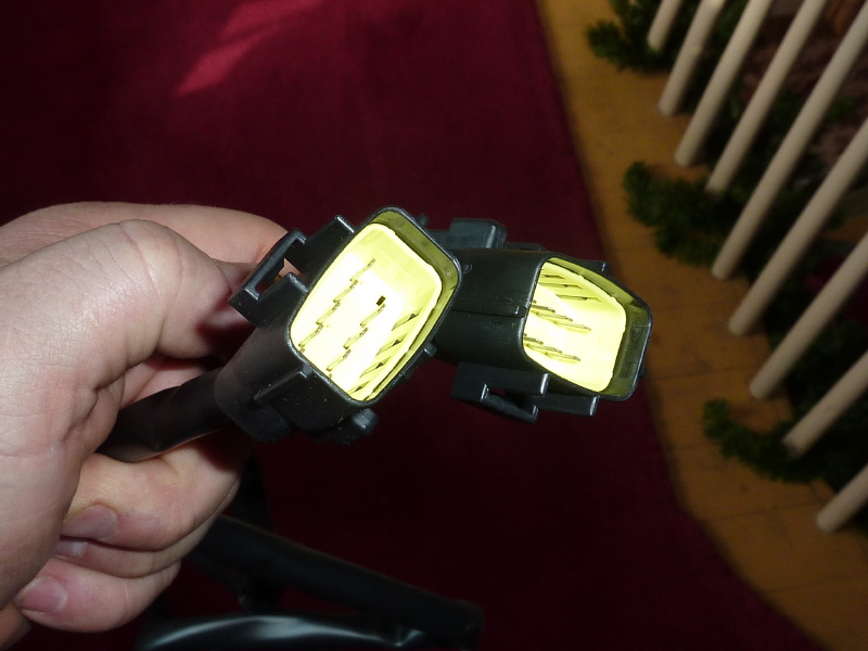
Here, both injector rail branches are shown |
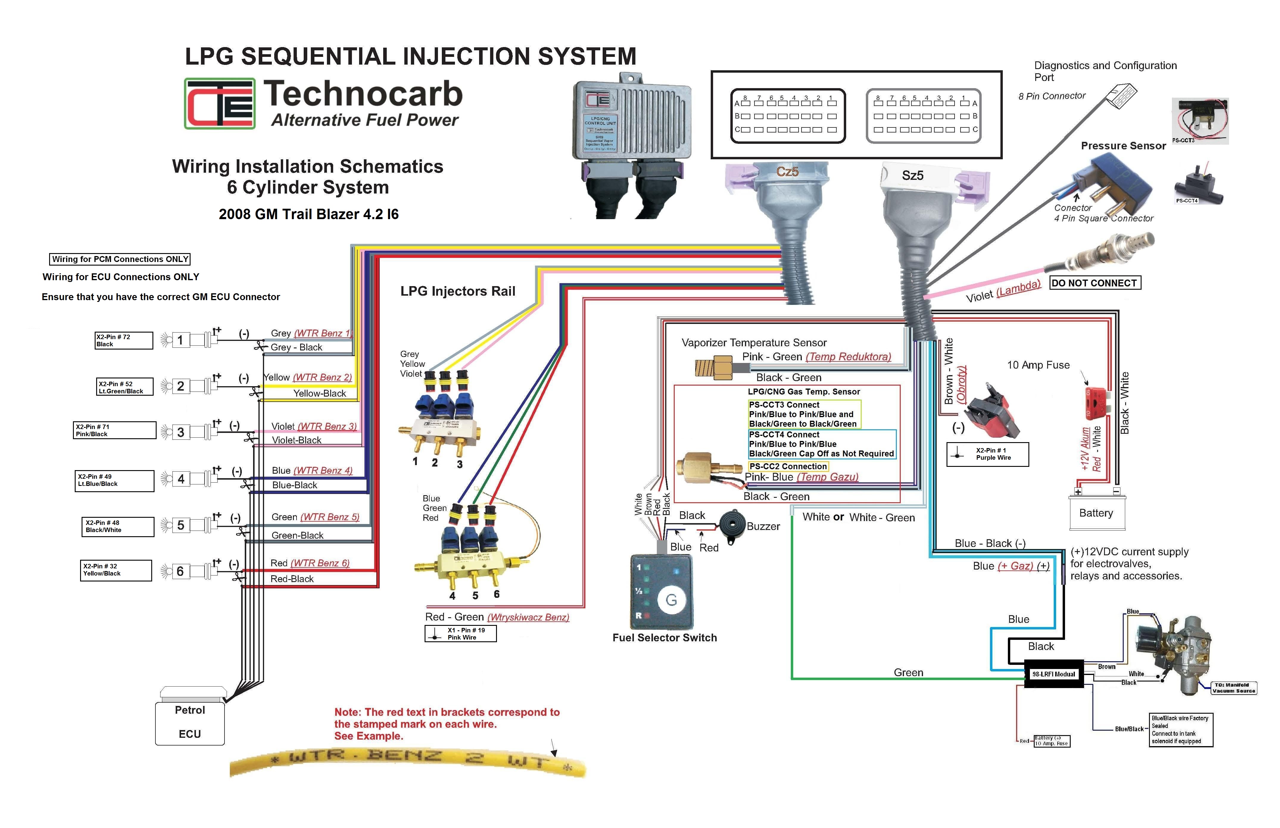
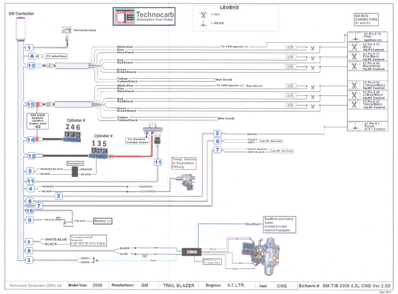
Wiring Installation Schematic (WIS) |
Electrical wiring problems
(Click any pic for an enlarged view)
For the sake of this document "WIS" refers to the Wiring Installation Schematic
Problem #1: The supplied wiring harness has two injector rail branch cables. On the CCS they are marked Harness #12 & #14. The combined harnesses have a total of 8 injector rail connectors and the application is an L6 with 6 injectors on two injector rails.
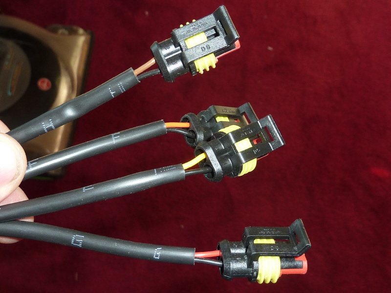
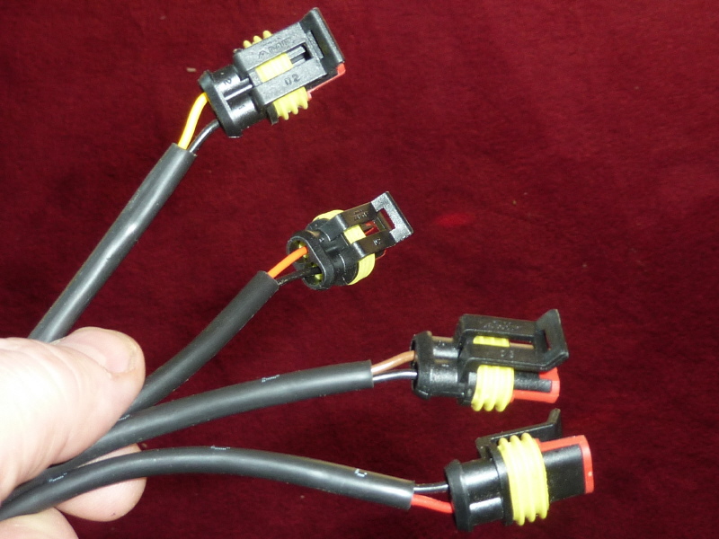
More Info: The wire colors of the 8 injector rail connectors
do not match what is shown on the WIS. The WIS shows 2 injector rails with 6 wires. However the wires shown are gray, Yellow, Violet, Blue, Green & Red. So when you look at the connectors (see pictures below) on Harness #12 & #14 their wires colors are Brown wire/Black wire, Yellow wire/Black wire, Red wire/Black wire and Orange wire/Black wire.
What is needed:
1. An updated WIS showing the injector rail connectors (shown below) connected to the injector rail pictures with color wires that match the existing cables (shown below).
2. An updated CCS showing the injector rail pictures with the correct cylinder number sequences.
3. On the WIS and CCS show which of the 2 cables has the red band on it.
4. Show which 2 of the 8 injector rail connectors are not used by their color wire.
Problem #2: The supplied wiring harness has two CNG Injector to Petro Injector Interface branch cables. On the CCS they are marked Harness #13 & #15. It will be difficult to explain the problem because the WIS, CCS and existing wiring harness branches are all different and do not match.
More Info: The problem here is generally the same as problem #1. To many wires, wires of wrong color and wires that do not match the schematics.
What is needed:
1. On the WIS, the gasoline injector pictures and GM injector wire colors look correct. The cylinder numbering also looks correct. However the pictured harness wire colors, shown on the WIS, do not match the existing wire harness (shown below).
2. On the CCS. The cylinder numbering on the injector rails looks like V6 and not L6.
3. On the WIS and CCS show which of the 2 cables has the red band on it.
4. On the existing wire harness (shown below) there are 9 wires per harness branch. Show which 2 wires are not used by their wire color.
5. Each of the Petro Injector Interface Harnesses have a lone red/white wire. Do each of these wires get connected together? Then connected to the common pink wire that is common to each gasoline injector. If this is not correct, please show the correct wiring.
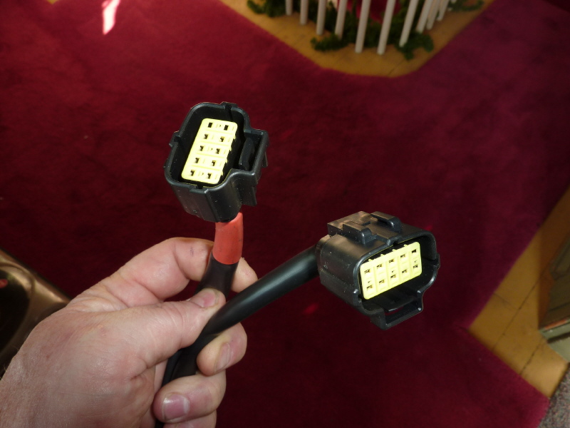
Here, both harness connectors are shown. |
Here are the matching connectors for the two wire extensions. |
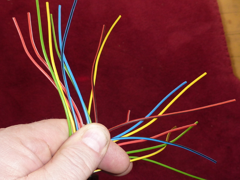
Here, both harness branches are shown. The wire colors are identical in both harnesses. Each harness has the following color wires: Gray/Gray-Black, Yellow/Yellow-Black, Violet/Violet-Black, Blue/Blue-Black, Green/Green-Black and Red/Red-Black. Each harness has an extra Red-White wire |
Component Connection Schematic (CCS) |
General Questions
1. The main wiring harness shown on the CCS Harness #X has a white-blue & black wires to be connected to a tank solenoid. The 98-LRFI fuel pressure interface also has a blue/black wire to be connected to a tank solenoid. Which one is correct?
2. The main wiring harness shown on the CCS Harness #2 has a brown wire to be connected to obtain an RPM signal. I will need assistance on where to connect this wire and how to find the location. My Trailblazer reference documentation does not help. I wish not to have to buy a $300.00 set of GM shop manuals.
2. On the CCS it shows a buzzer wired to the Fuel Selector Switch. My kit did not come with a buzzer. Does the Fuel Selector Switch have a built in buzzer? If not and I have to supply my own buzzer, can you provide the specs on the buzzer?
3. On the CCS the 98-LFRI is shown. It's RED wire is shown connected to a 10A fuse and then to the battery. Also the BLUE wire shows another 10A fuse in-line. Since the fuses were not included in the kit, are they needed? if so, are these user supplied items?
4. My kit included a "SVIS Universal Installation Guide" for V6 & V8. There are a variety of topics and instructions that are misprints or incorrect. Do you have a "SVIS Installation Guide" that matches the CCS?