
Why a Cylindro-Conical Fermentor
The conical bottom is a 60° angle from the cylinder wall. The slope is just the right angle so the trub, dead yeast cells, and everything falling out of suspension will slide to the bottom at the apex of the cone. The trub can be drained with a minimum waste of good beer. No siphion is needed when racking as the side port is always below the bier line.
Design Criteria
List of Material
The Building Process
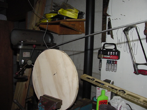
I started out with a piece of 1 1/2" x 3/16" x 6' steel bar bent around a 3/4" plywood form the diameter of the fermentor. I then opened my vice 6 inches and layed the semi round ring across the opening. Hammering and rotating the ring, at the center of the vice, until it was close to the plywood form. |

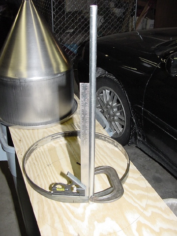
The semi ring was measured, cut and welded together to form a complete ring. At this point the ring was slid over the fermentor. Then the high and low spots were hammered out on the vice until the ring slid over and down to the lid opening with no binding. |
To cut costs, I used 1/2" electrical conduit to make the legs and support trusses. Each leg was notched and flattened slightly to clear the fermentor body. |
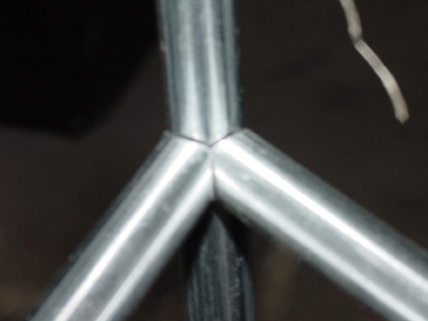
Each leg was clamped and trued vertical before being welded at 120 degrees apart around the ring. |
The fermentor was then slid down into the emerging stand and dimensionally checked for clearance and fit. |
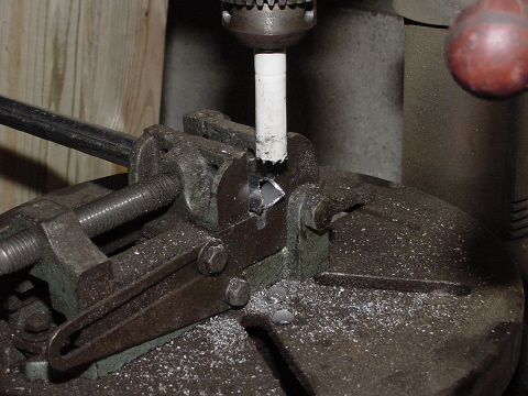
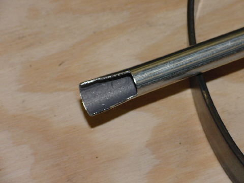
Once proper fit was established it was time to fabricate the support trusses. Three pieces of 1/2" electrical conduit were cut to rough fit. With the help of a 5/8" bi-metal hole saw chucked into a drill press, I cut each support truss to form half moon ends. |
Two cut per end were needed to make the ends match up nice and snug. A little de-burring and filing cleaned things up for welding. |
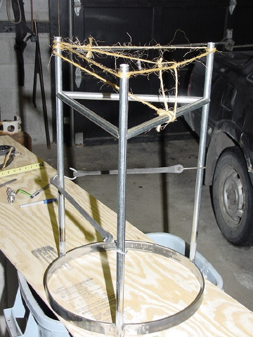
The support trusses were then fitted on the vertical legs, leveled and tied off with binders twine to hold them in place. Each truss is tack welded in preperation for the final weldng. |
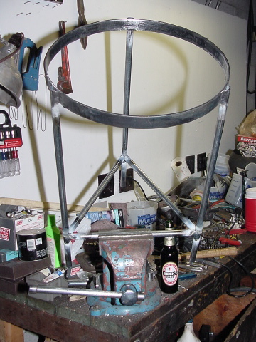
Once the tack welding is done, the stand is then transfered to the vice for final welding. In the vice, it can be repositioned in any angle for the best access. Note the Becks Dark in the backround. My inspiration for this entire project. |
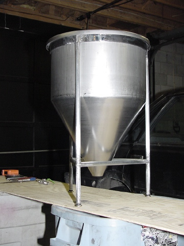
Here is a look with the hopper body dropped into the welded stand. It nice when a plan comes together. |
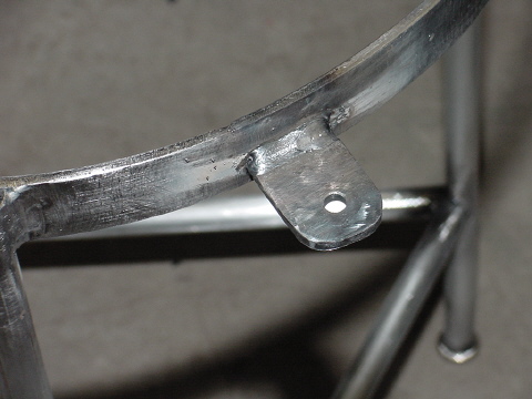
The next task at hand are the tabs that hold the clamping bar to the stand. I used a left over piece of the ring to make the tabs. There is nothing like a 1/8" full flow electrode at 175 amps to lay down the near perfect bead. |

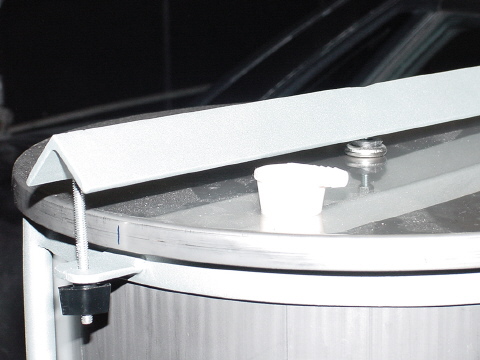
The clamping bar is made from a piece 1 1/2" x 3/16" angle. A 1/4-20 threaded connector is welded at the center for the one of the leg pads to seat against the top of the lid. |
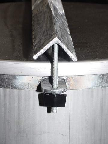
At each end of the clamping bar a hole is drilled and taped. 1/4-20 thread all is then screwed in and adjusted to height, cut and tack welded from the top. Note the thumb nut to adjust the clamping pressure. |
A view of the clamping bar in place. At the bottom of each leg is a 1/4-20 nut, fitted into the end and welded. This provides the leg pads something to screw into. |

Here is a view of the stand after two coats of primer and two coats of texture paint. |
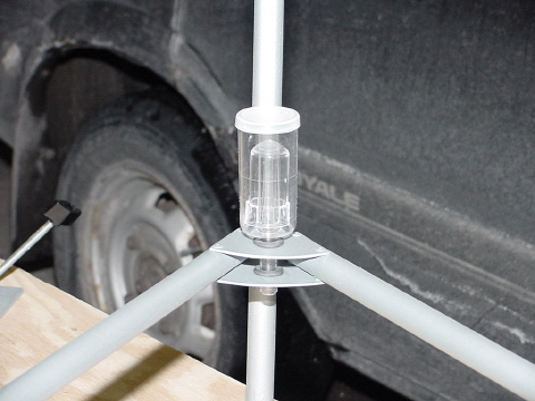
Here two aluminum plates are cut, drilled for the 7/16" grommets and pop rivited in place. If you struggle for head space in the refrigerator/lagering cabinet, the air lock can be transfered down here. |
Here is a view of the Rubber stopper. A 1 1/4" bi-metal hole saw was used to cut the hole. The lid was clamped onto the drill press table and lots of water was used to cool the hole saw. |
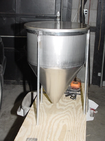
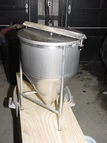
An Assembled view |
Another assembled view |