|
The Fuelmaker C3 has been around for many years. I do not have exact information
on its introduction, however I have a copy of the Patent on the compressor module
which dates to July 9, 1991. It's service longevity is a testament to its design and excellent durability. The idea of using the C3's as the front
end on this project stems from the fact that I have three of them and the safety
features it has to offer. Here is a partial list of safety features that the C3
has to offer. Any of these conditions will cause the unit to shut down.
|
Click on any picture to get an enlarged view!
|
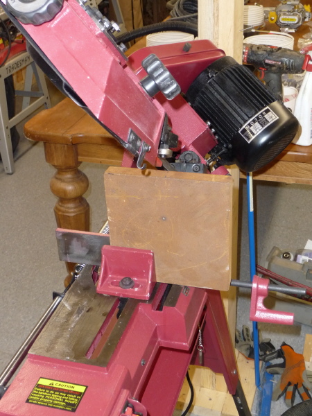
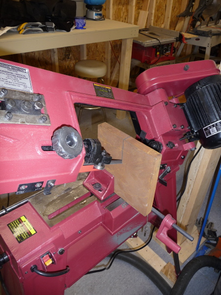
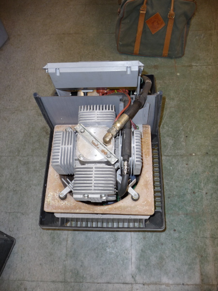
Here is a view of the Nardi Atlantic 100 sitting on the chopping block. |
After removing a bunch of socket head cap screws, the air shroud comes right off. The fan assembly is a fairly aggressive unit. With tons of pitch, it will move a ton air for cooling purposes. |
|
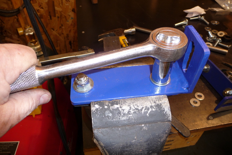
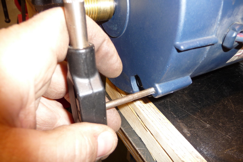
Remove the set screw or wind it out far enough to clear the threads. Unfortunately the set screw is impaled into the threads. This makes removing the fan assembly hard. |
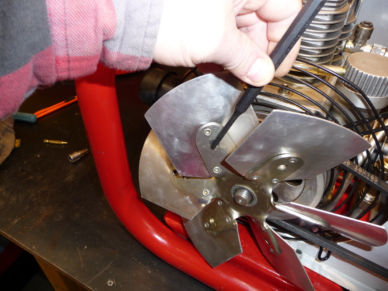
A slight tap on the fan will break the assembly free. |
Once passed the bad threads, the fan assembly will wind off with a single finger. |

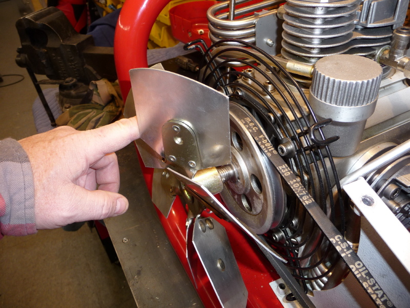
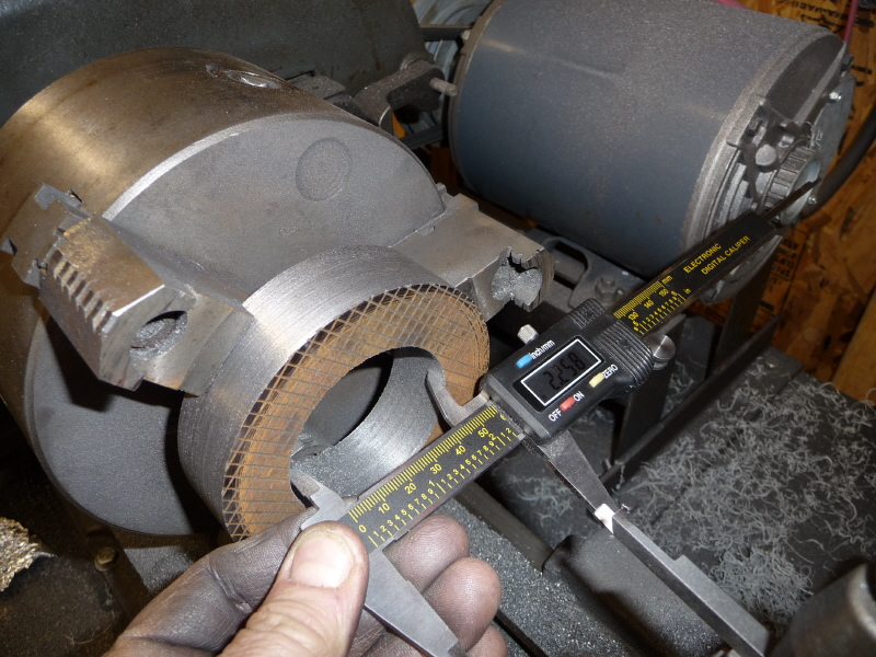
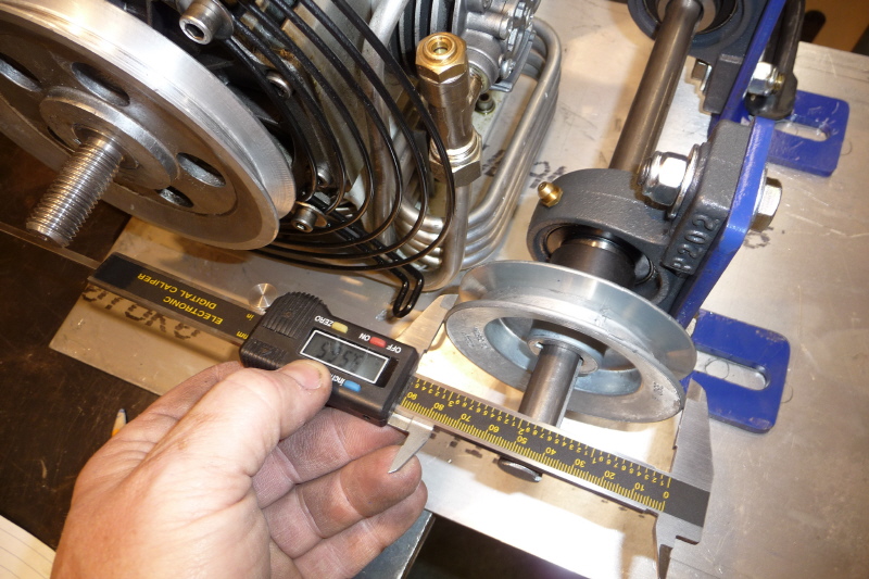
Once the fan assembly is removed, I measured the outside diameter of the driven pulley. It was 5.375 ". |
|
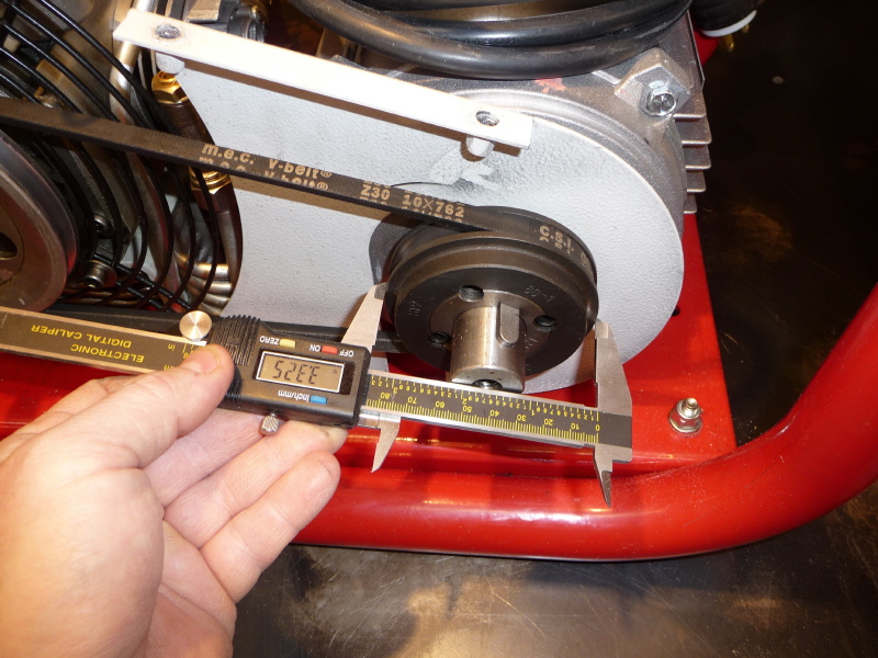
I then measured the diameter of the drive pulley. It measured 3.325". |
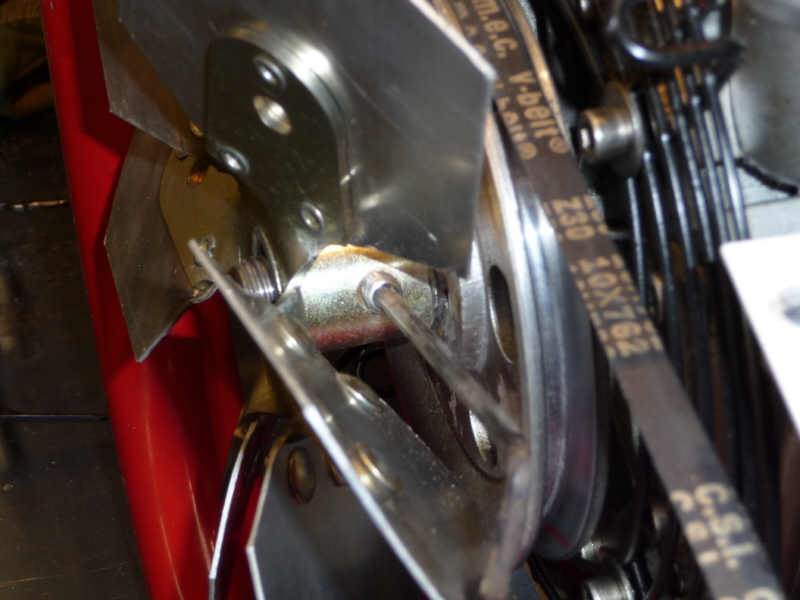
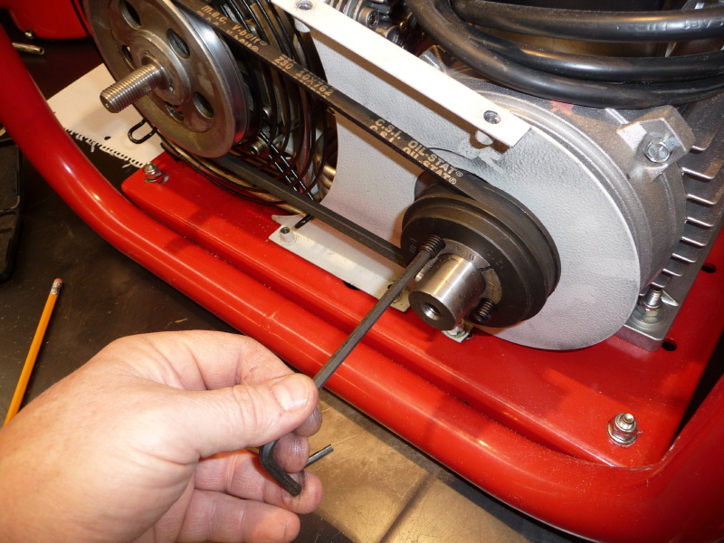
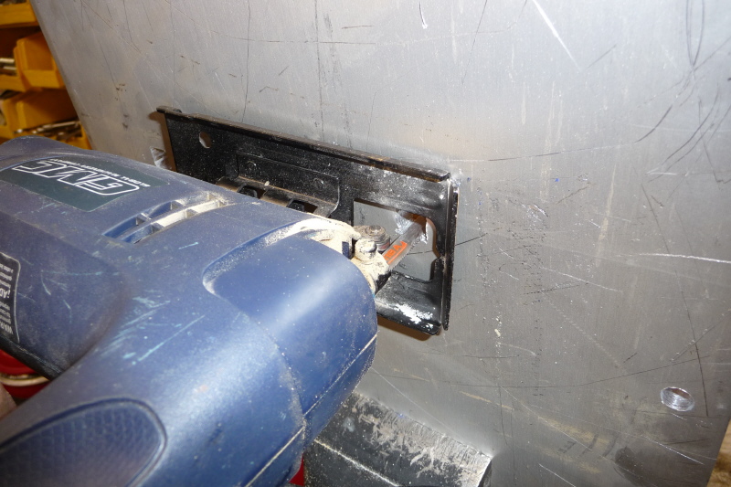
You will need to remove the set screws |
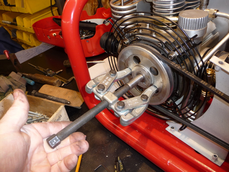
I used an S&K tools gear puller to pull the driven pulley
out as far as you could with out damage to the drive belt. |
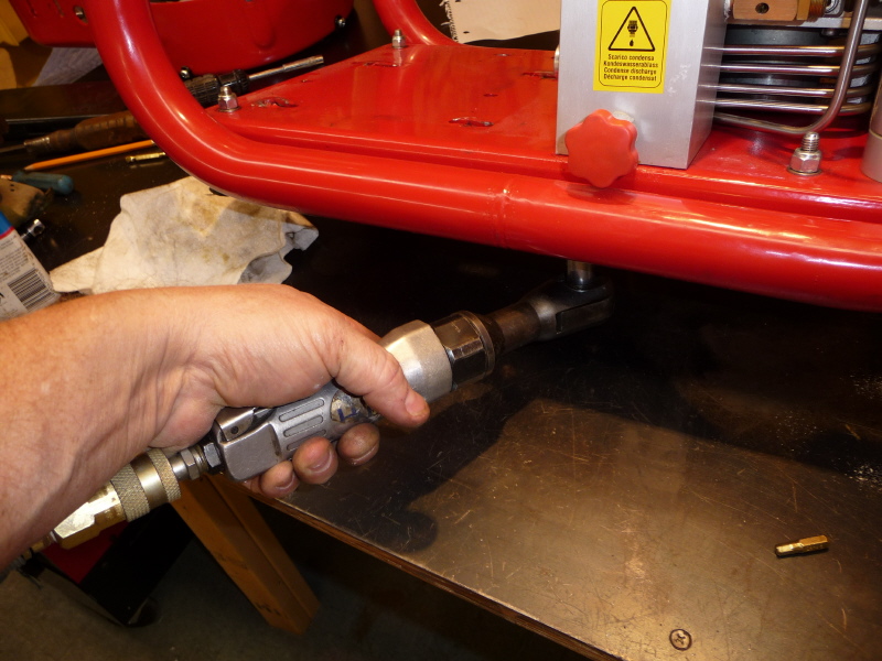
Here I switched the puller arms from inside to outside. Then pulled the drive pulley off. With that, the driven pulley came right off by hand. |
|
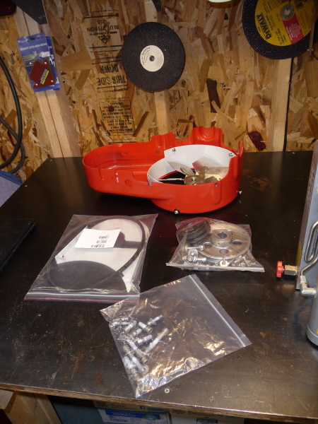
A couple more socket head cap screws and the pulley and fan guard came right off. |
Here I bag up all the loose parts. I have a |
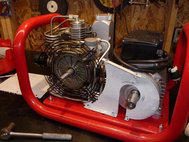
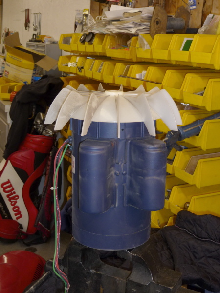
Here is a shot with the motor removed. |
Next we need to remove all the socket head cap screws from the air dryer, water separator and the compressor body. |
Since everything is connected together with |
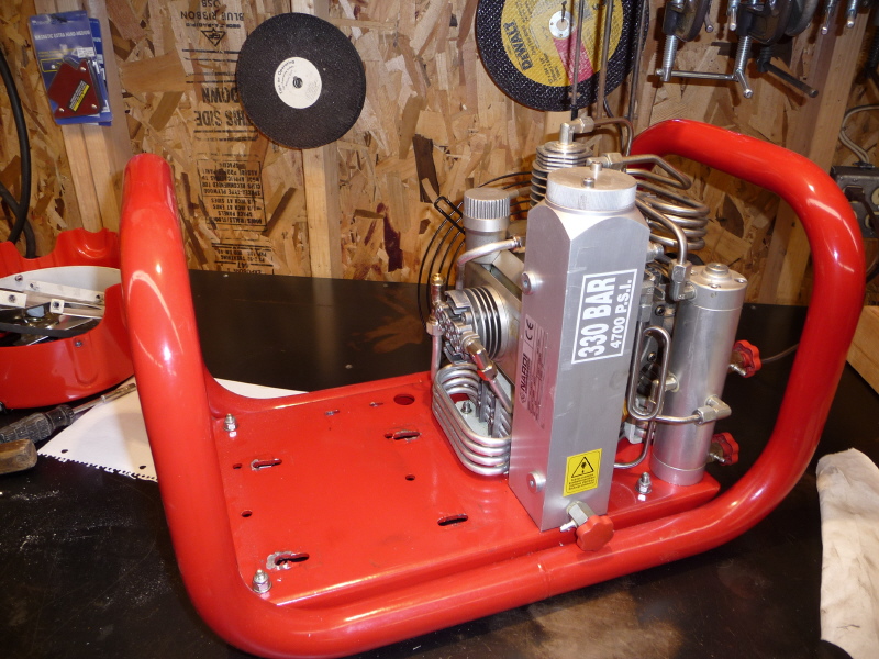
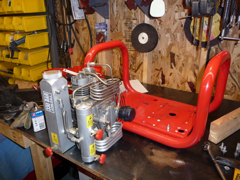
Here the unit sits removed from the mounting cradle. |
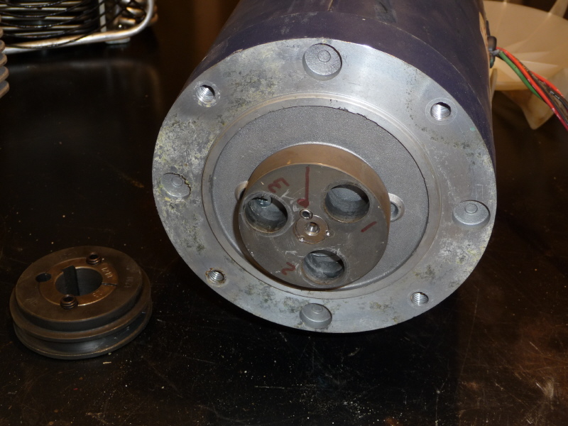
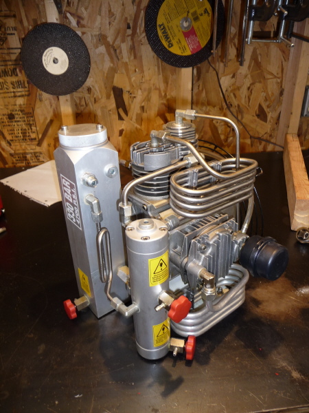
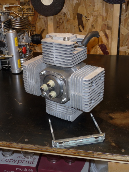
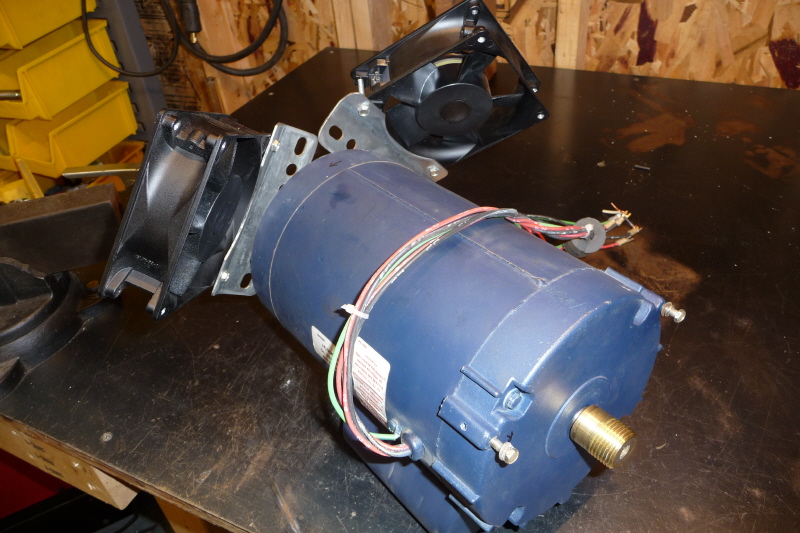
With the Nardi compressor unit removed, it was time to start on the C3. Here is a shot with out the outer shell. |

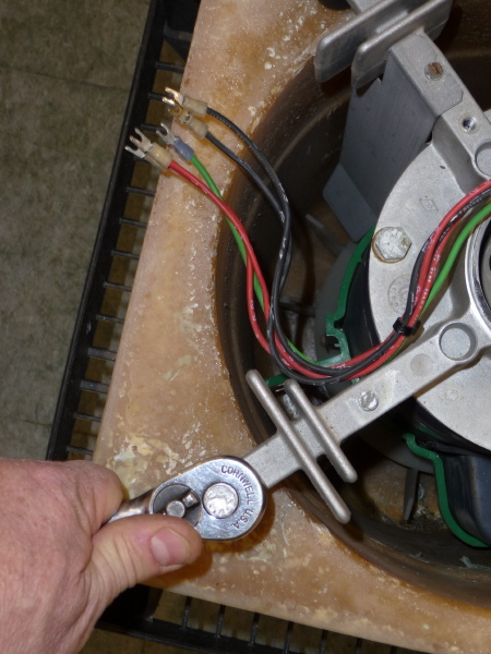
Here I am removing the low pressure line. It is funny how half the parts are metric and the other half are english. |

Here I am disconnecting the high pressure line from what I think is a check valve assembly screwed into the high pressure stage of the compressor module. |

Next I removed the C3's timer mechanism. |
|
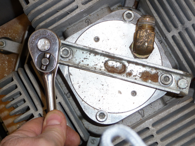
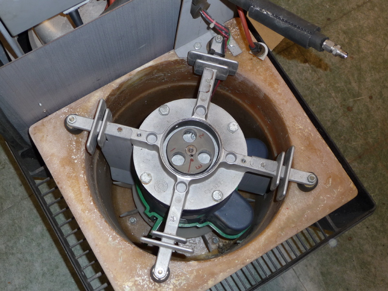
Next is the the compressor leveling bar. Remove the two bolts and the bar just lifts off. You can just lift the compressor module right out. |
Here is the compressor module looking from the bottom. If ever replacing the module, you must make sure that the dimple in the middle of the leveling bar lines up with the dimple on the top of the compressor module. When tightening the bar, the right or left bar edge can not touch the top of the module. If it does, your bearings will wear out. Trust me on this. |
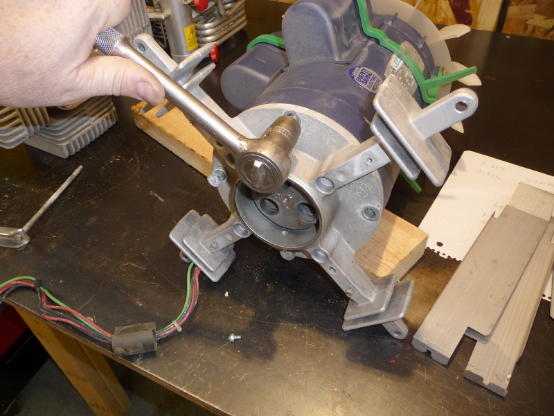
With the compressor module removed, we can now start working on the motor mounts. |
Remove the four bolts at each corner and the entire unit will just lift out. |
|
Remove the four bolts that hold the motor mount onto the motor and the motor mount will just fall off. |
Here is the cooling fan assembly. It just screws onto a pressed brass threaded sleeve. |
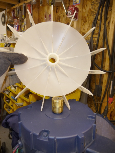
Here is a better look at the fan and sleeve. |
I realized there was not going to be an easy way to attach a pulley to this mess. So I decided to make a pulley. That's right just make one! This is the Little Metal Shop you know. |
|
I decided to make the pulley out of cast iron. Cast iron will allow me to use High Speed Steel tool bits instead of carbide. This is very important when grinding and shaping a tool bit. |
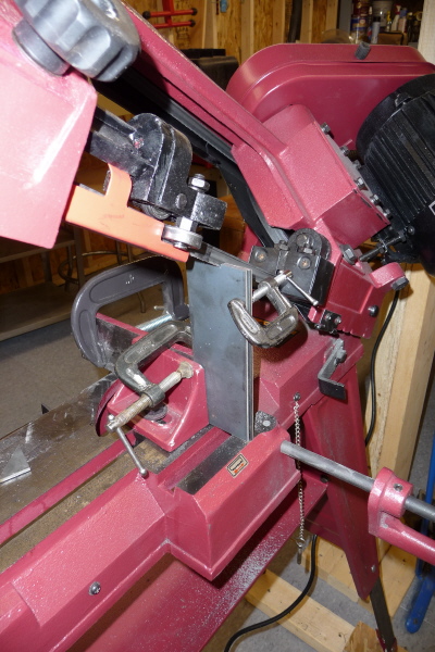
I dug up a 1" thick lapping plate that I savaged from a flea market years ago. Then chucked it in my metal cutting hacksaw. Here is the first cut at it. |
 Here is the second cut. The metal cutting hacksaw does not cut very fast, however if you have time on your hands it does a great job. |
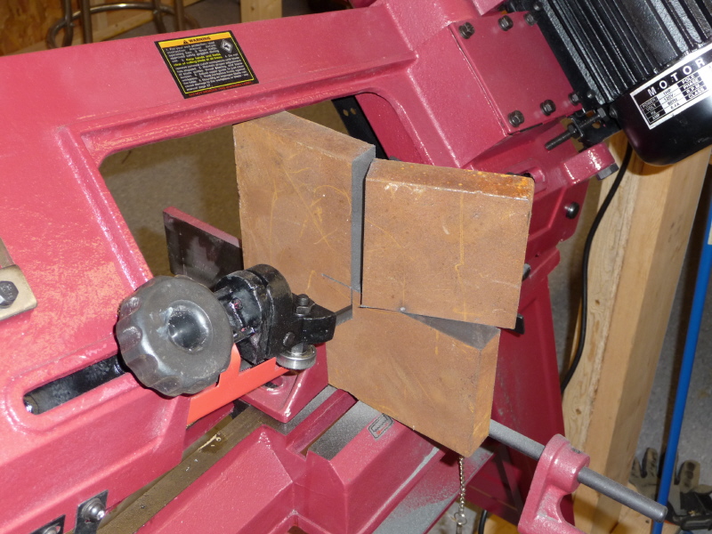
The raw block is done being cut and ready for some machining. |

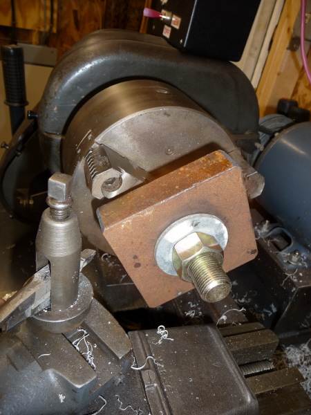
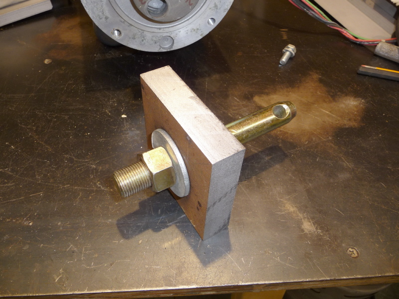
I needed a way to chuck the raw block in my lathe. This is an extra hitch pin for my three point round bale spear. It has a threaded end to screw down on the block and a round end to clamp in the 3 jaw chuck. This was a nice find. |

Here is a view of the crush washers and a matching drill bit that is the same diameter as the threaded end. Got to love a plan when it comes together. |

Here I center punch a starter hole in the middle of the block. |
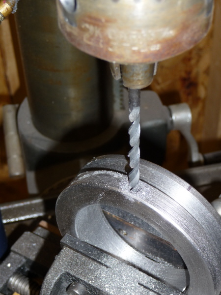
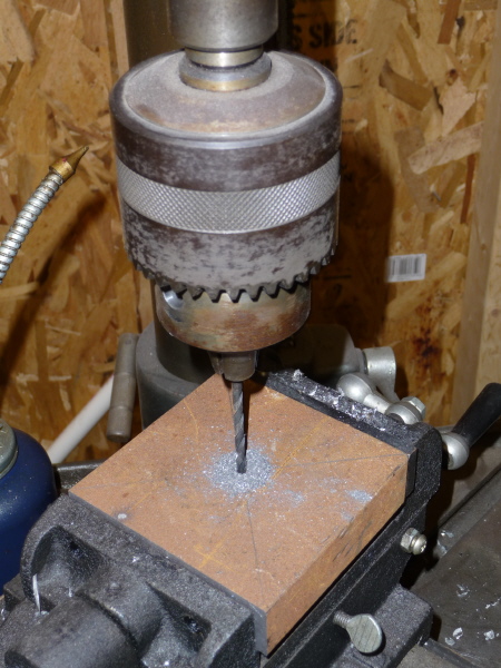 I then drill a small pilot hole in order to get a good center spot to drill from. |
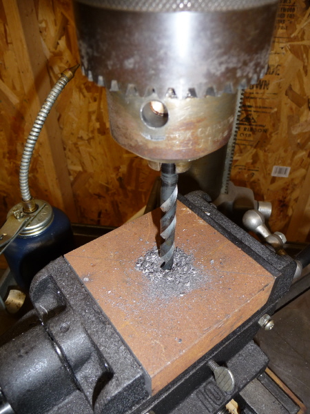
I drilled it a little larger hole in prep for the final drilling. |
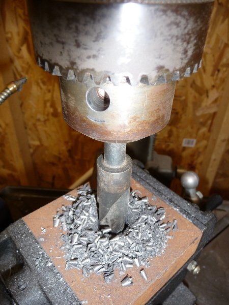
Here the final drill bores its way through the plate. |
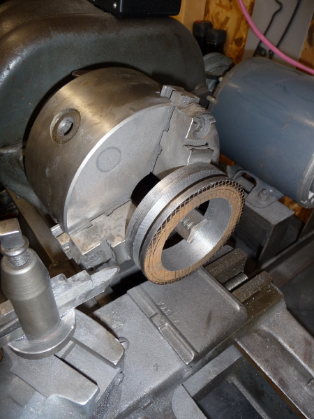
A quick clamp up and we are ready for some lathe work. |
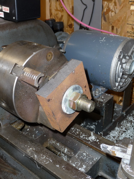
Here the block is gripped in the chuck and preliminary clearances are checked. You do not want the block striking anything once you start cutting. |
|
You need to take very small bites of the block. To much and you will wreck the tool bit. |

We are making headway. The picture is of the block spinning and metal flying. |
Here we are nearly finished with the outside diameter. I am using a carbide tipped tool bit. This way I can spin the block at a higher rpm and get a smoother cut. |
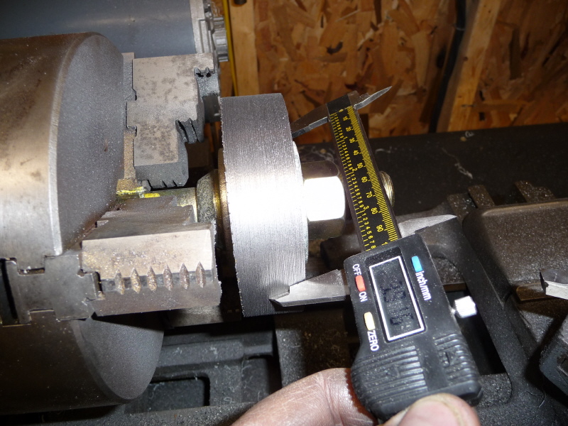
The digital mic says we are close to where we want to be. |
|
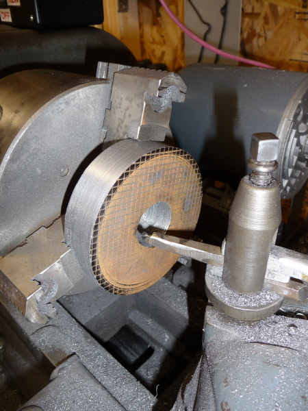
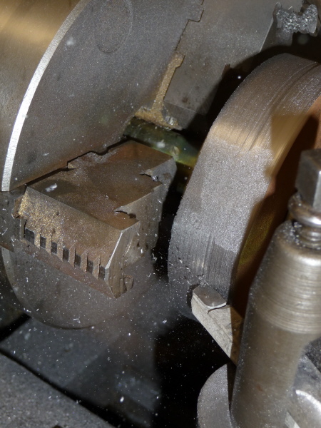
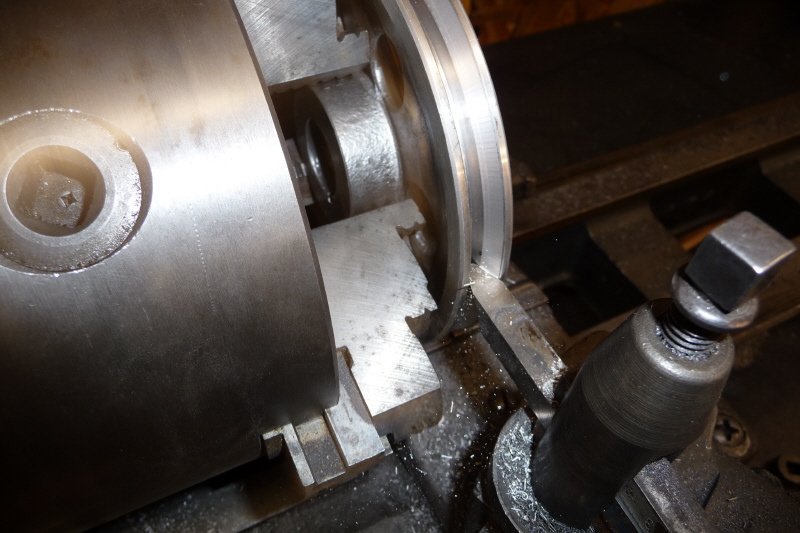
Here the hitch pin is removed and the raw pulley is clamped by the outer chuck arms. I ground a small boring bit to cut the inner diameter out. |
The boring continues and continues and continues. |
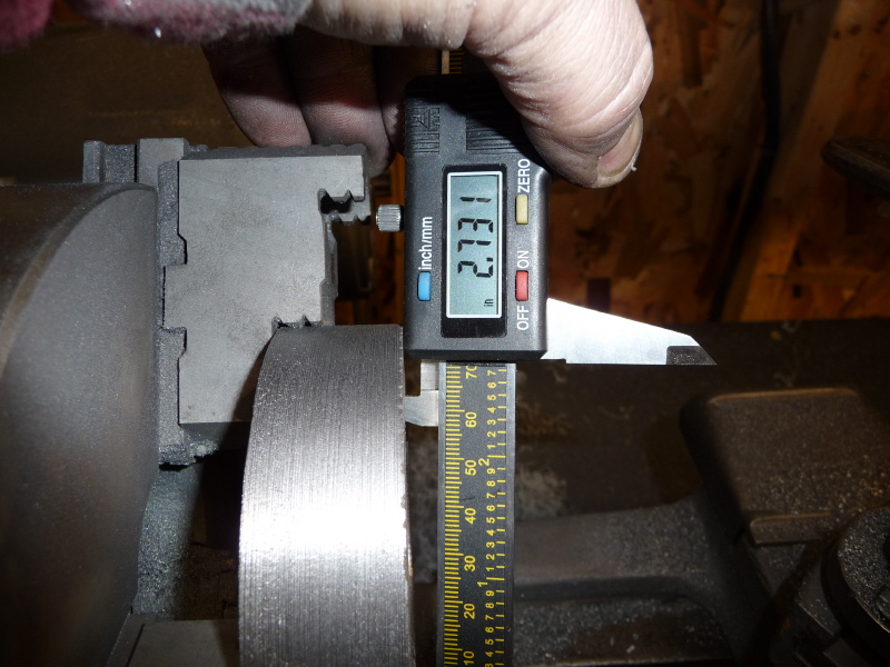
A quick check indicates that we are getting close. |
At this point it is a continuous process of shaving a little off, stopping, checking the diameter and shaving a little more. |
|
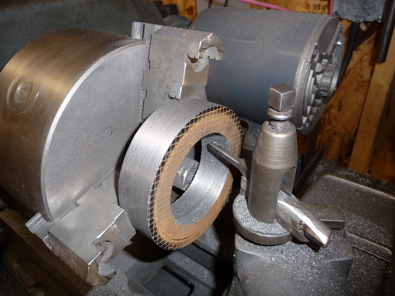
We are finally at the correct diameter. |
A quick fit up indicates a perfectly tight fit. I needed to lightly sand the inner diameter to get it to slide on with rubber mallet taps. |
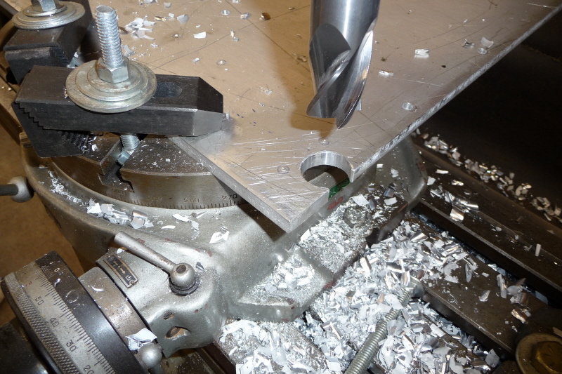
 Here I took a raw piece of HSS tool stock and began the tedious task of shaping it into the form of the "V" belt pulley groove. After truing up the tool post and tool bit with the raw pulley, we begin to cut. |
After cutting the groove to the proper depth, a little polishing with stainless steel wool finishes of the groove. |
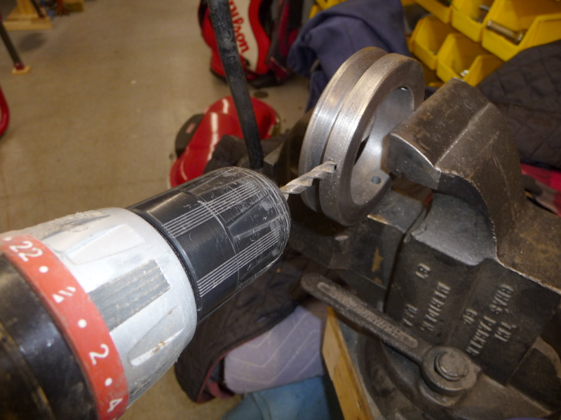
Here the pulley is marked at 0°, 120° & 240°, then drilled using a #7 drill bit. #7 (.201} is the tap drill size for 1/4 x 20 cap screw. |

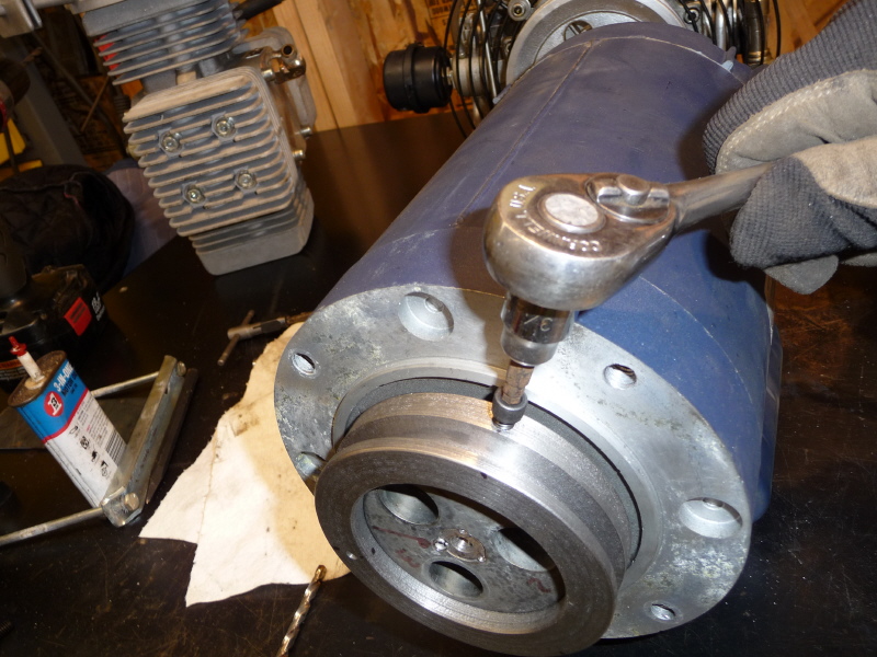
I then slid the pulley onto the motor hub. Using the existing pulley holes as guides. I drilled the hub to about 3/4" depth. I found some nails that fit the hole snuggly and used them to keep all the holes in line. |
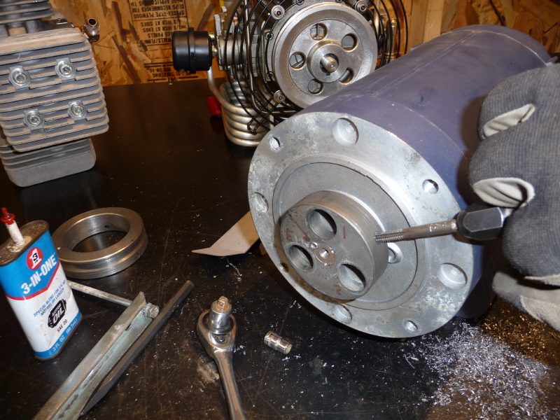
Once the drilling was done, I tapped the motor hub holes to 1/4 x 20 threads. I used Moly-Dee Tapping Fluid when cutting threads. Castrol, the oil company, makes it. |
Here I chased the pulley holes with a 1/4" drill to allow the socket head cap screws to pass through the pulley and screw into the hub. |
I placed a small drop of 242 Loctite, the blue kind, on the screw threads of the 1/4 x 20 socket head cap screws and tightened them down. |
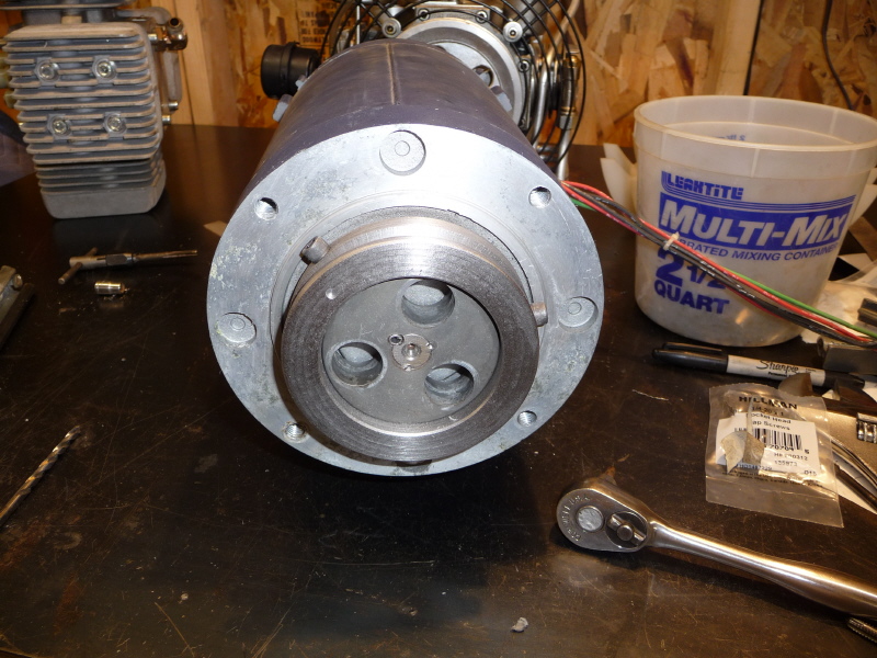
Here is a shot of the finished pulley mounted on the motor hub with all the socket head cap screws in place. |

With the pulley finished, it was time to begin work on the motor brackets. Here I am cutting a 6' piece of 1/8" bar into workable size pieces. |
The pieces are then cut to length in prep for being sawed to width. |
|
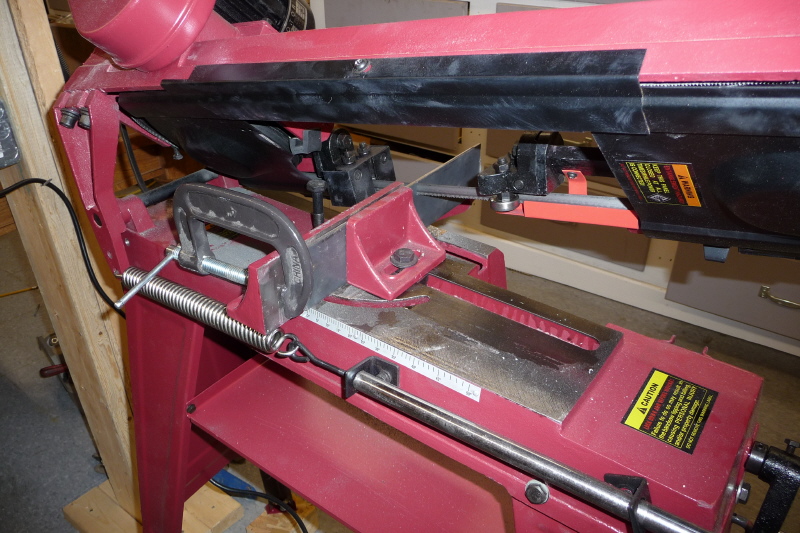
Here I clamped 2 pieces of bar together for rigidity and sawed them to width. |

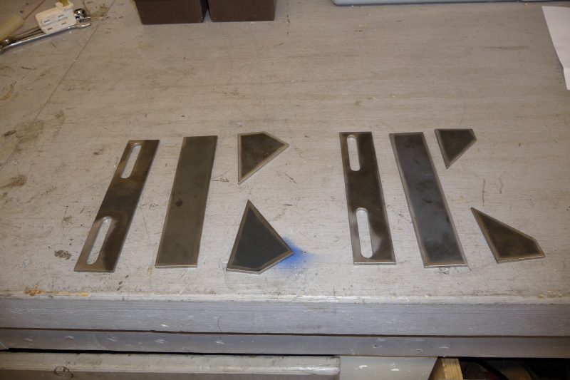
After all the sawing is finished, here are the pieces. I used AutoCAD to draw up the details of the brackets. Then cut the paper pieces for templates. Drawing to scale rulez! |
|
After tracing the paper templates, I flat clamped a piece of bar to cut the motors bracket extension tabs. A total of four are needed. |
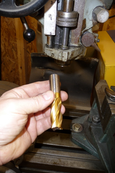
In order to mill adjusting slots in the brackets. I am going to use a 3/4" end mill to square up the edges of the motor mount brackets. The pieces must be square to properly clamp in the mill vice. |
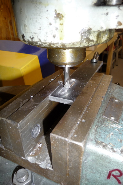
Both front and rear bracket pieces are chucked in the mill vice and their top edge is being milled. |
Once the top edges are done, a spacer is set into the vice and the two pieces are flipped and the other side is milled. |
Both slot pieces are now clamped by the milled edges. I used a flat washer to determine where to start the slots. |
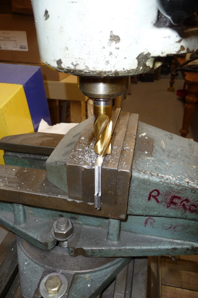
Here is the work on the first slot. |
Here is work on the second slot. |
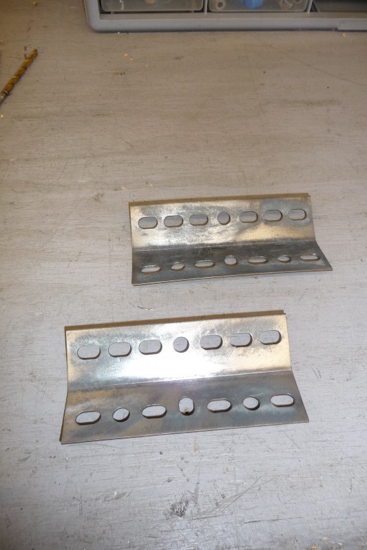
Here is all the pieces for the front and rear motor mount brackets all laded out. |
Here is a preliminary fit up of the front bracket. |
Here both front and rear brackets are fit up and ready for TIG welding. |
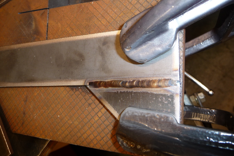
This is the fri st TIG pass on the rear bracket tab. Not my best effort, however some slight adjustments will correct that. |
Here the bracket is flipped and the other tab is welded. |

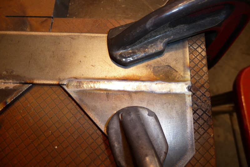
Here is a finished view of the welded tabs. Notice how smooth and clean the weld is. There is no grinding, sanding or cleaning with a proper TIG weld. |
Once the tabs are welded on, the slotted piece is clamped up and readied. |
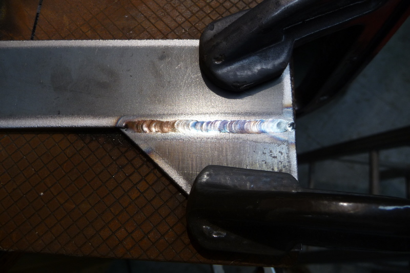
Here I used a 2 x 4 piece of wood to rest my hand on as I weld. I did not count on banging into a clamp which caused a stop in the weld. |
I added an over kill fillet weld on the other side of the bracket. At this point the rear bracket assembly is finished. |
On the rear side of the motor are two nice bosses that can be drilled and tapped to attach the bracket to. |
Here is a view with the rear bracket attached. |

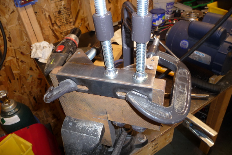
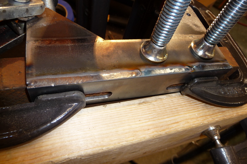
I was thinking of clamping the front bracket to my assembly table, however the thin metal skin top warped under the heat. |
So I clamped it to a block of cast iron and welded away. A near perfect TIG weld will require no grinding, filing or sanding when done. |
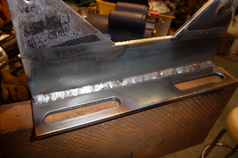
Here the bracket is flipped and the backside welded. |
Once the tabs are welded on, I using the original motor mount as a template to mark the motor mounting holes. |
Here is a reverse view showing the mounting holes. This will make drilling and alignment of the motor mount flawless. |
This is the final clamping of the front motor mount before it is TIG welded. If you do not over clamp welded assemblies, they will warp. I always go overboard to prevent warping. |
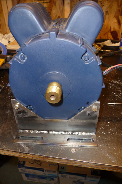
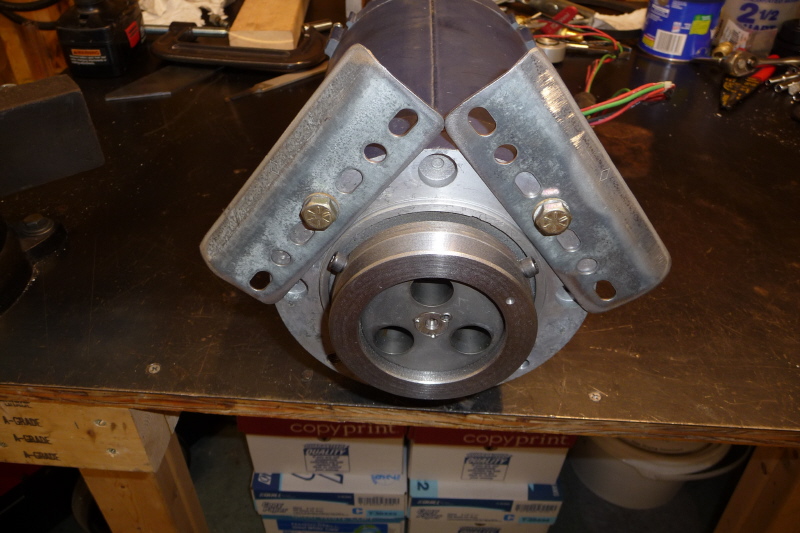
Here is a front view of the motor mount all welded and assembled on the motor. |
At this point I needed to fabricate brackets to hold the replacement cooling fans. I cut two pieces of light angle from a piece that I found in my scrap steel bin. |

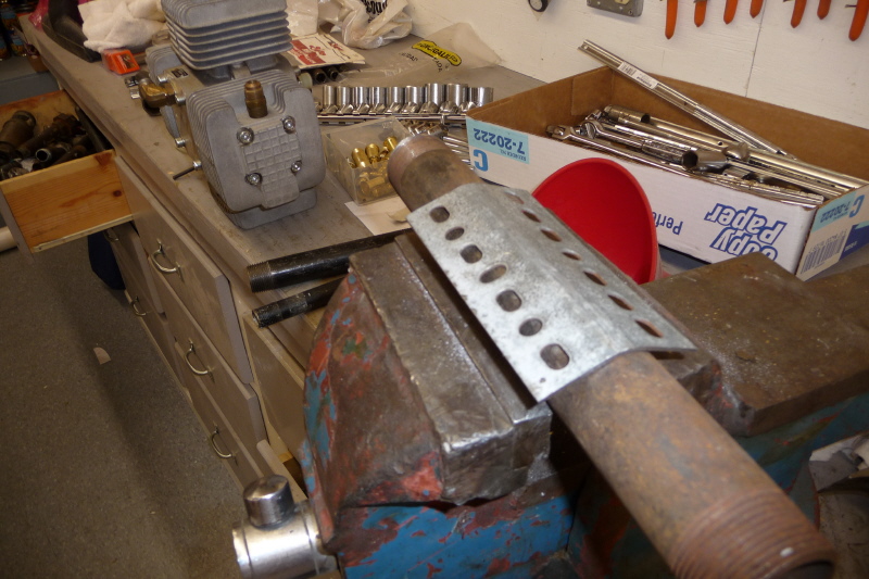
I then chucked up a piece of 2 1/2" steel pipe and began hammering the angle out of square. |
Here I keep hammering and test fitting the bracket. I keep this up until the correct angle was obtained to mount the cooling fans. |
This is the finished bracket. I rounded the edges with my table grinder and wire wheeled the entire piece to rough it up for painting. |
This is a quick fit up in order to check the clearance of a mounting lip on the front of the motor. |
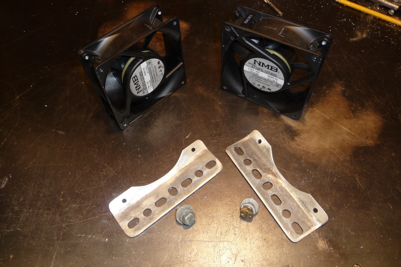
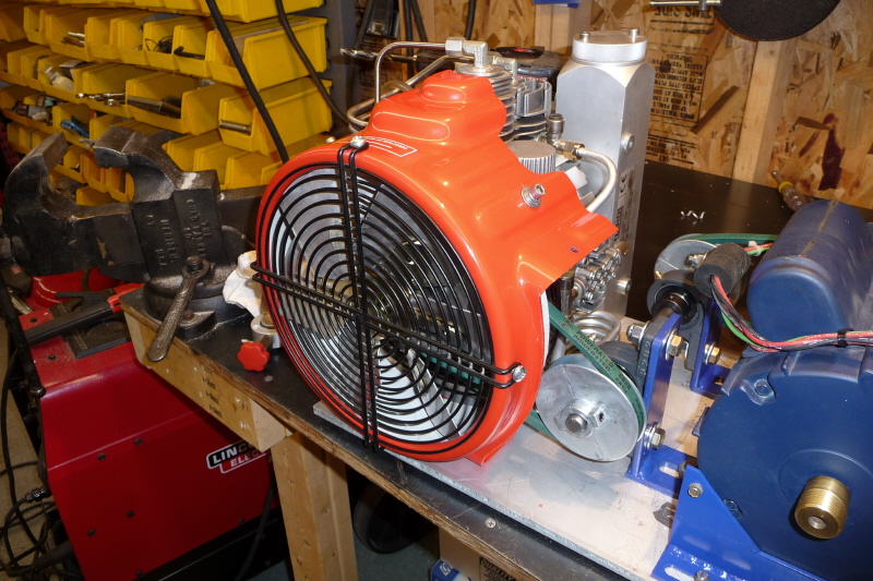
Here are all the needed parts for the motor cooling fan assemblies. |
Here is an assembled view of the cooling fans from the pulley side or front. Each cooling fan flows 110 CFM for 220 CFM total. |
I really have no way of knowing what the cooling requirements for the motor are. However I purchased 4 fans from Surplus Supply and will just add two more, if needed. |
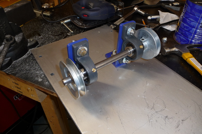
Here are the basic parts for the jackshaft. The 5/8" diameter shaft comes with a slot already machined in it. Sweet! |
The 5/8" shaft came 36" in length. I chucked it in my electric hacksaw and cut it to rough length. |
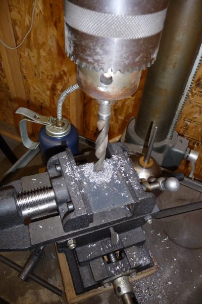
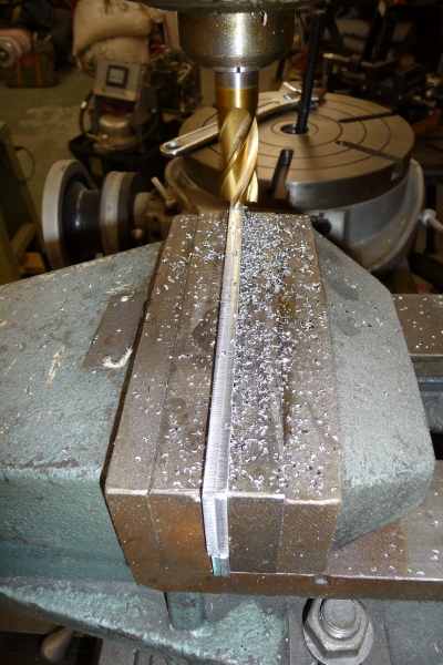
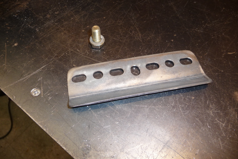
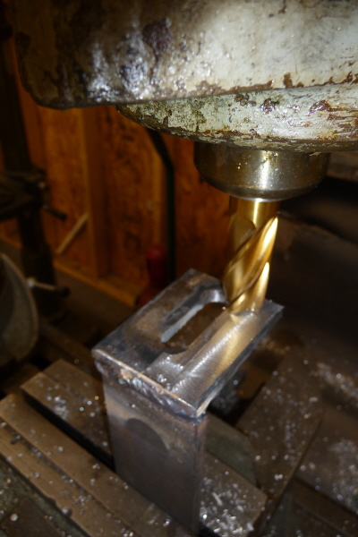
In order to make the jackshaft assembly slide adjustable, slots need machined in the pillow block bracket. Here I am drilling pilot hole in the bracket base. |
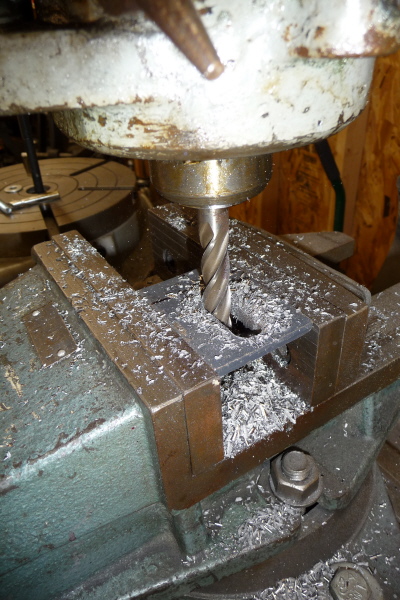
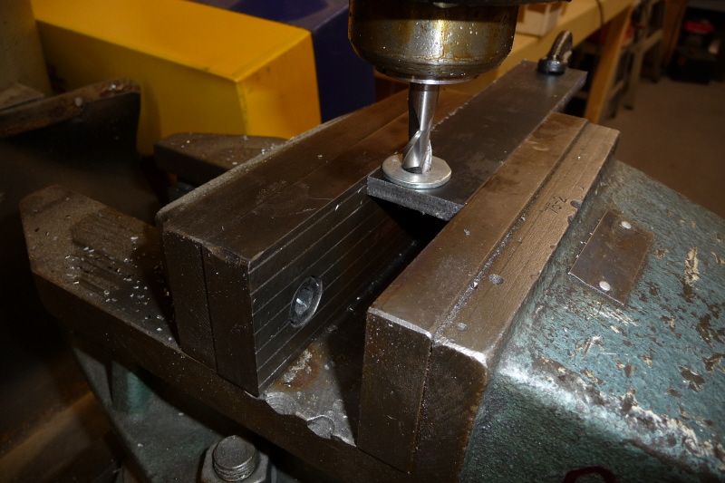
With the pilot hole drilled, I chucked the piece in my milling machine. I then ran the end mill through the hole and cut the slot out. |
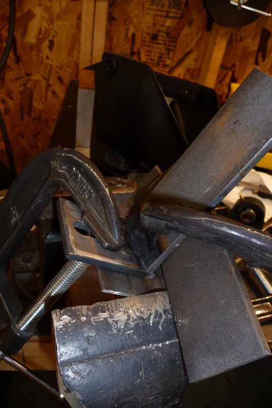
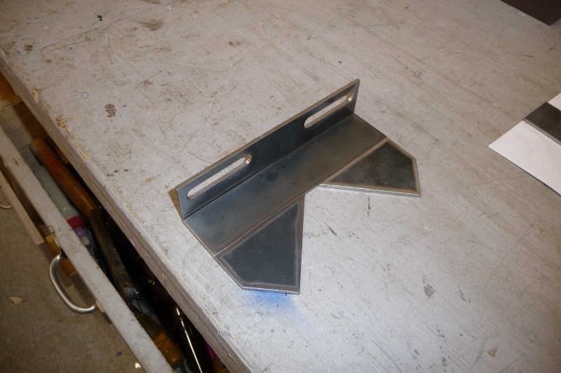
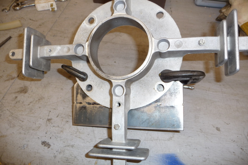
Here I am positioning the bracket pieces at a 45° "V". This will create the ideal situation for the coming weld. |
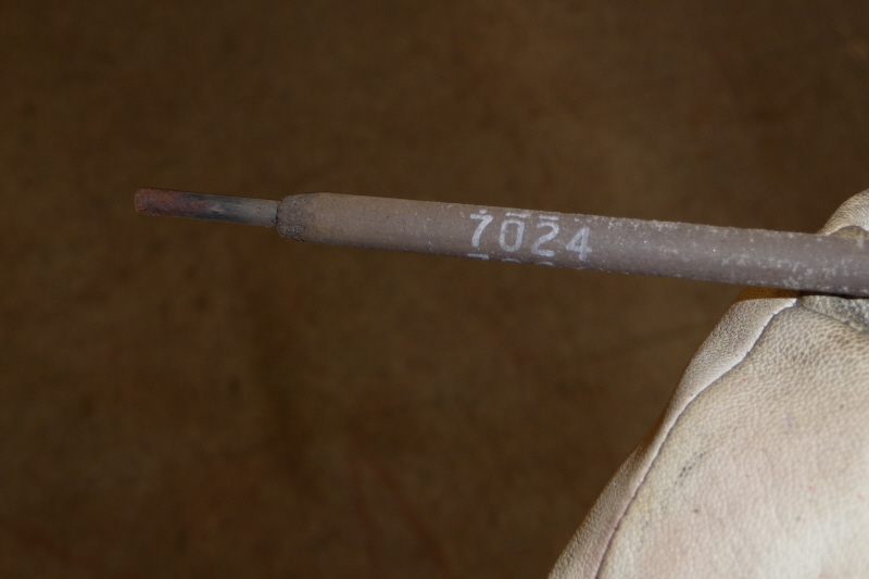
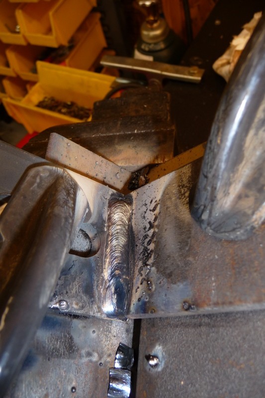
I have decided to DC stick weld the bracket pieces. There is no finesse needed here. With thick metal, a 7024 rod and a lot of amperage will do the trick. |
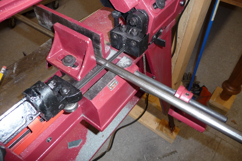
Here is a view of the finished fillet weld. The high amperage assured maximum penetration. Notice the mess stick welding makes compared to TIG. |
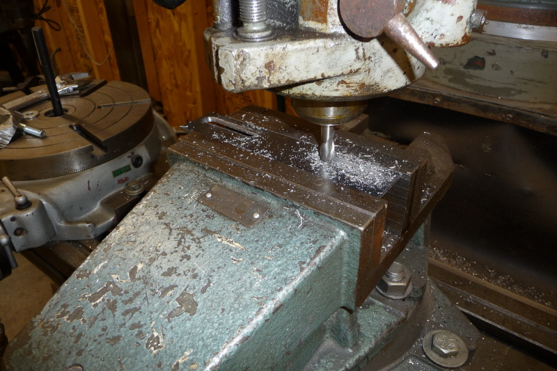
I am milling the bottom of the left bracket flat. It had a slight warp to it. The other bracket was "OK". |
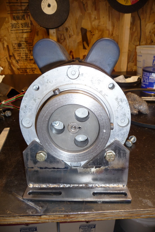
This view shows the bolting of the pillow block to the angle bracket. I used nylon lock nuts to deal with any vibration issues. |
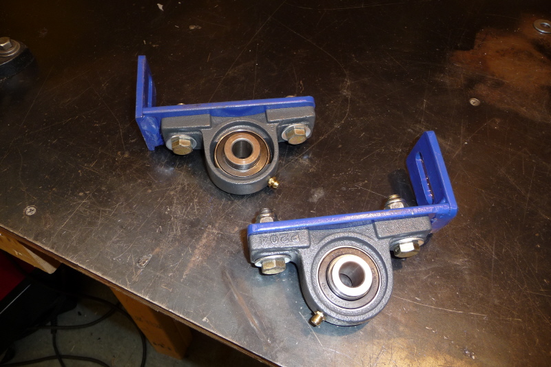
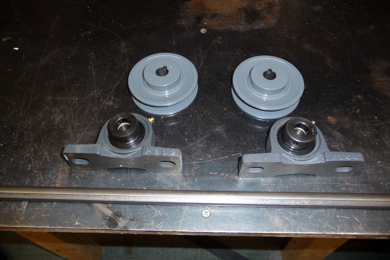
Here are the completed pillow block assemblies ready for install. |
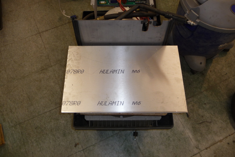
The bulk of the fabrication has been completed, so it is time to begin the component layout. I started out with a piece of aluminum plate 26" x 18" x 3/8" and just set it on the fiberglass motor shroud. |
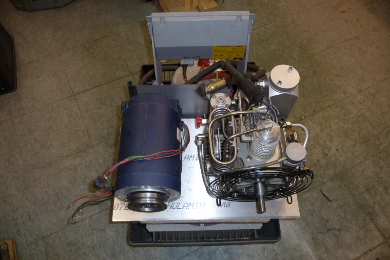
Here I set the compressor and motor where I though it looked good. |
I set the jack shaft in place and began moving the parts around to find the optimum location and proper alignment. |
With the motor marked and removed, the jackshaft is next and then the compressor. |
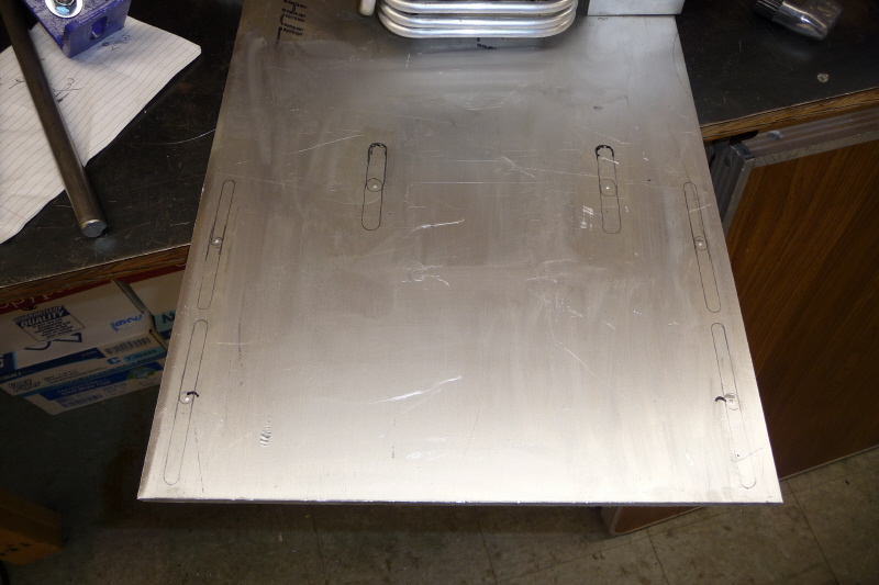
Here are pencil slot marks which show the possible minimum and maximum travel of the motor and jackshaft. This will allow maximum travel when the belts are installed and adjusted. |
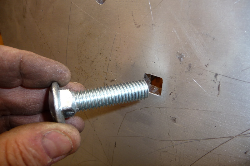
I decided to use carriage bolts to hold down the motor and jackshaft. A pilot hole was drilled and a jigsaw was use to make the square hole. |
A small amount of filing trued up the square hole for a tight fit. I had to tap the carriage bolts in with a hammer. |
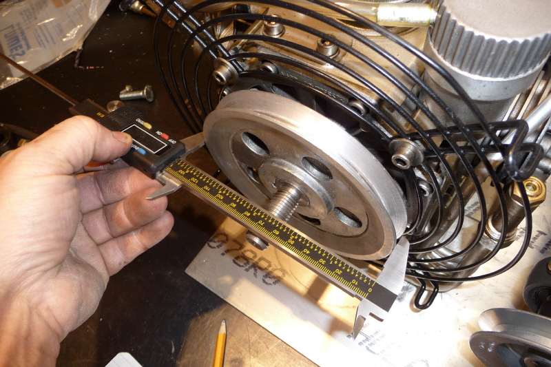
Here I am measuring one of the jackshaft pulleys in preparation to calculate the belt length. This is a link to a web site which has a nice pulley calculator. It does belt length, pulley ratios and RPM calculations. |
Along with the drive pulley diameter, you need the driven pulley diameter. |
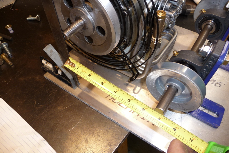
And last you need the center distance between both pulleys. With this info a belt length can be calculated. |
Here are the two belts I will need for the drive system. |
One thing I noticed was that the compressor pulley was designed for a metric belt. So I chucked up the pulley in my lathe and cut the groove width to 1/2". I used the same tool bit to cut the groove in the motor pulley so they would match. |
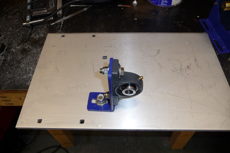
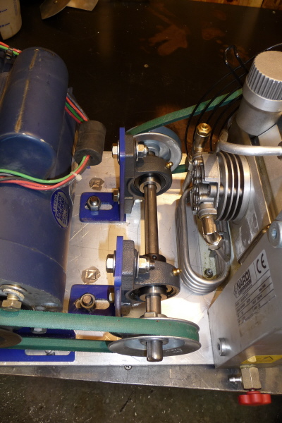
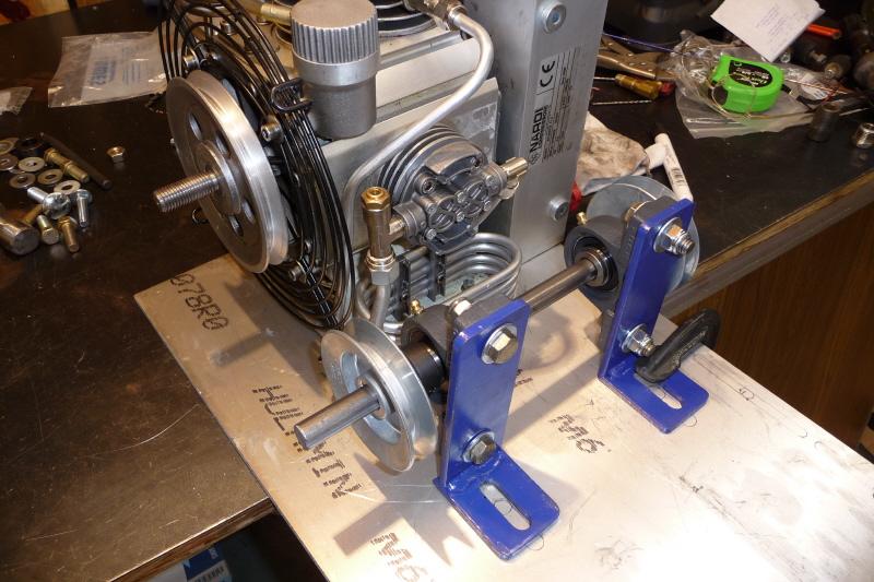
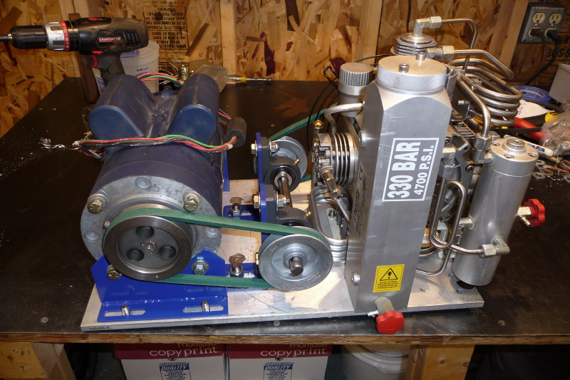
Now it is time for the final fit up and assembly. Starting in the middle with the jackshaft. |
Once the jackshaft is bolted in place, the motor and compressor module just drop in. |
Here the pulley belts are added. At this point I noticed that the compressors water/oil separator has a mounting boss on the bottom. I will need to machine some clearance for it. |

So I clamped the aluminum base onto my Phase3 rotary table and mounted up a 1" end mill. |
Here I cut out the required hole clearance. The water/oil separator boss is a recessed fit. |
It looking like everything is good to go. |
The jackshaft and keyways still need to be cut to final length. So I am doing it here. |
Ugh, I forgot about the fan shroud. Using a band saw, I cut the motor end off and filed the rough edges. Then drilled new holes in the base plate to screw the shroud down. On the top of the shroud, the existing holes were used. |
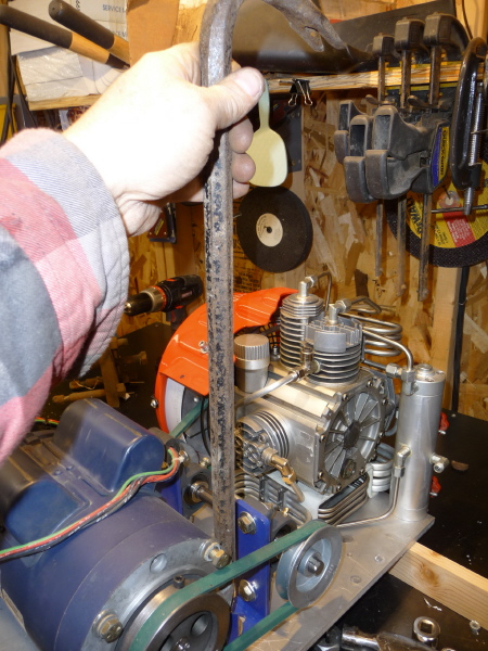
Here I am using a crowbar to tighten the belts for final tightening. I may have to re-design this as it is not trick at all. |
Well, the final assembly is completed. I removed the unit from the work bench and set it in place on the motor shroud. At this point I am ready to secure the compressor assembly to the shroud using the original rubber standoffs. |
After locating the final position of the compressor. The old C3 motor mount bracket is used as a template to drill the holes for the rubber standoffs. |
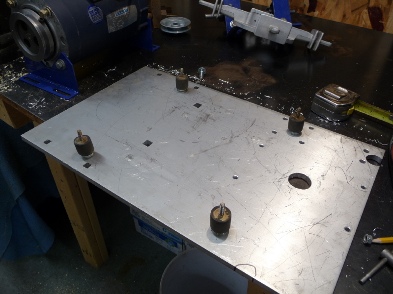
Here the holes were tapped and the rubber standoffs screwed into the mounting plate. The mounting plate will now fit nicely into the existing fiber glass motor shroud. |
Here is an assembled view showing the rubber standoffs connected to the shroud. |

Here I used automotive black plastic loom from an old Cavalier that I salvaged to cover the 220v and motor temperature wires. This makes routing clean and protects the wires from damage. |
I need to supply 120v to the cooling fans. Here I am making a small wiring harness using "Push on Terminals". The connections will be soldered and shrink tubing used for isolation. |
Here is the finished harness. |
I ran the wires inside black automotive loom after connecting the "Push on Terminals" to the fans. The black loom was routed over to the motor where the fan wires were tucked into the existing larger loom. |
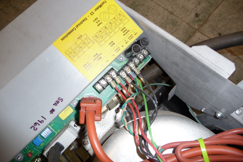
I decided to tap one leg of the existing 220v from the C3's electronic module. This tap would be on the switched side. So the fans start when the compressor motor energizes. |
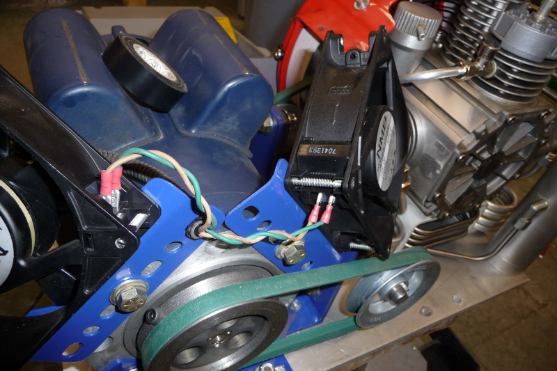
Here is a view showing the wire routing and wire connections to the electronics module. |
Here is another view from the front. |
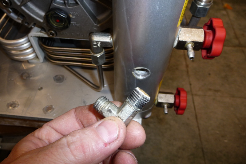
Here I removed the high pressure fitting from the exit port on the moisture separator. There is some type of hardened sealant on the threads. I had to chase the threads with a pipe tap to clean them up. This was typical for all the connections. |
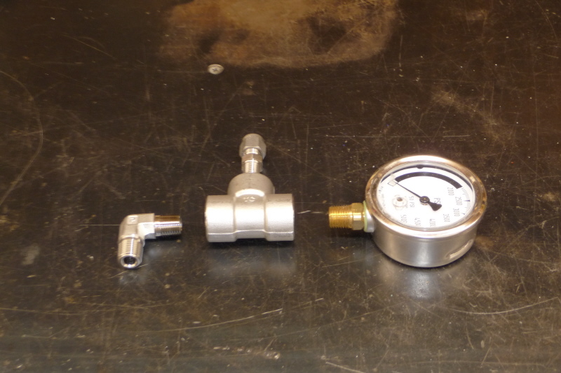
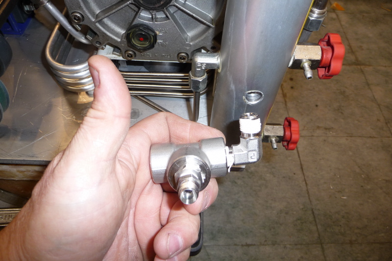
Here is an exploded view of the piping to be installed on the exit port. I am adding a high pressure gauge for monitoring purposes. |
I assembled the street elbow, tee and 1/8" double ferrule compression fitting before installing into the exit port. |
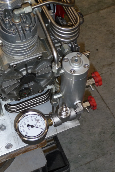
This is the final assembly mounted, showing the pressure gauge facing up. |
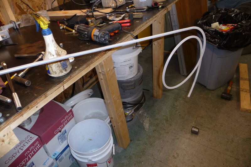
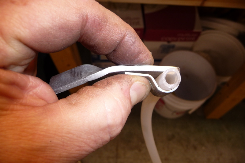
Here I am sliding 1/8" stainless steel tube into a piece of plastic hose. The old C3 high pressure line was encased in a rubbery coating. This is a duplicate effort. Wipe the line with a little WD40 and warm it with a heat gun. It will slide on effortlessly. |

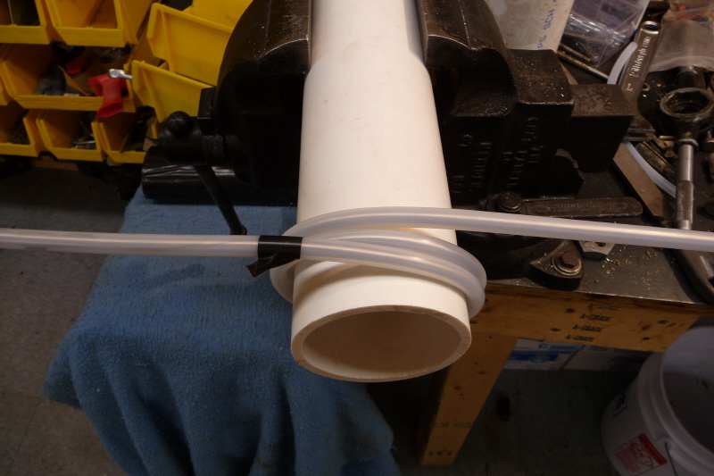
I am using a piece of 3" PVC plastic pipe, chucked in a vice as a form. This makes clean sweeping bends with out damage to the stainless steel tube. |
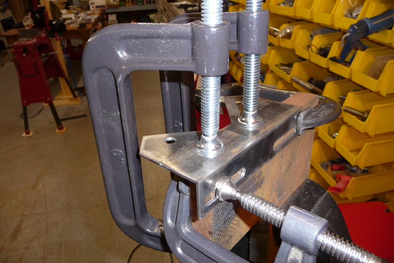
I needed to design a clamp that could be bent to some obscure angle and secure the high pressure line in a perpendicular fashion. This is what I came up with. |
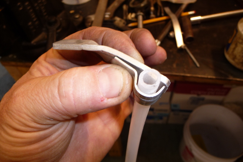
Here is another shot of the clamp. I used self taping screws to mount the clamp and secure the clamp bar to the clamp base. |
Here the first clamp is installed on the high pressure line as it exits the C3 manifold. |
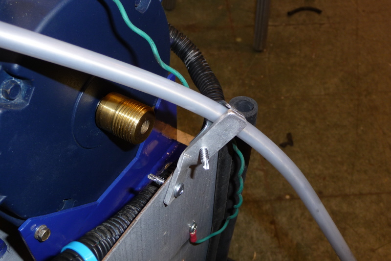
The next clamp is installed at the top of the compressor before it heads to the compressor exit port. |
Using the 3" PVC pipe I bent a tension relief coil. This will relieve tension and vibration stress between the rubber mounted compressor and stationary C3 base. |

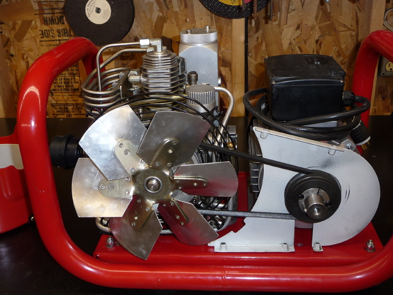
Here is a front view showing the high pressure line routed along the right hand side and over the top. |
Here is a rear view showing the tension relief coil routing and connection to the exit port. |
Here is another view from the side. |
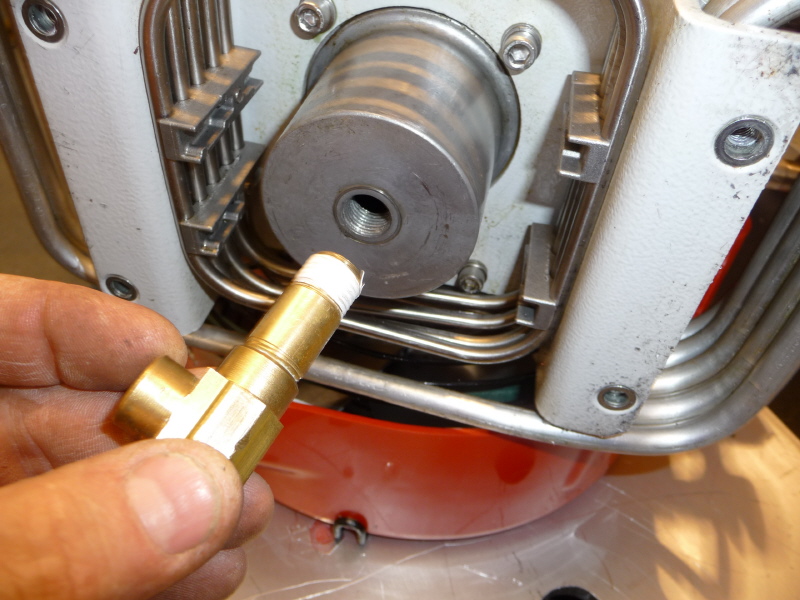
On the bottom of the compressor is a sump in which the oil drain plug is located. I replaced it with some brass piping and a ball valve for quick oil changes. Here is the pipe nipple and 90° elbow ready for installation. |
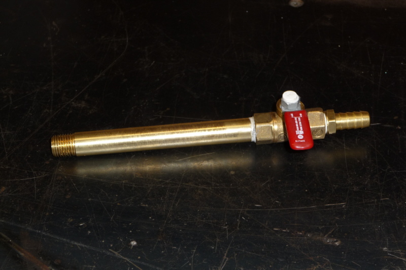
Here is the pipe, valve and barbed hose fittings assembled and ready for install. |
Here is a view showing the oil drain piping installed. |

Another view |
I never liked the way the 220v line entered the C3, so I installed a 2" x 4" utility box to contain the 220v wiring. |
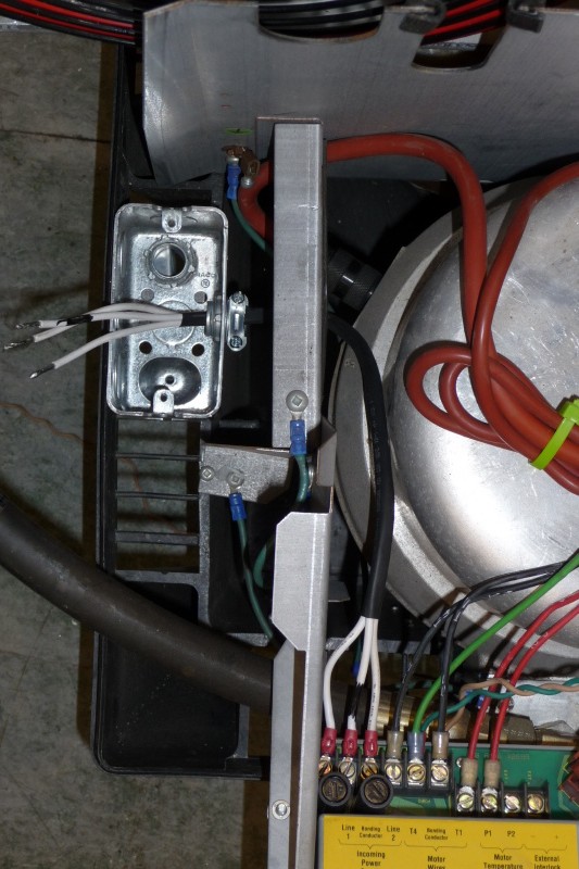
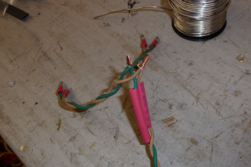
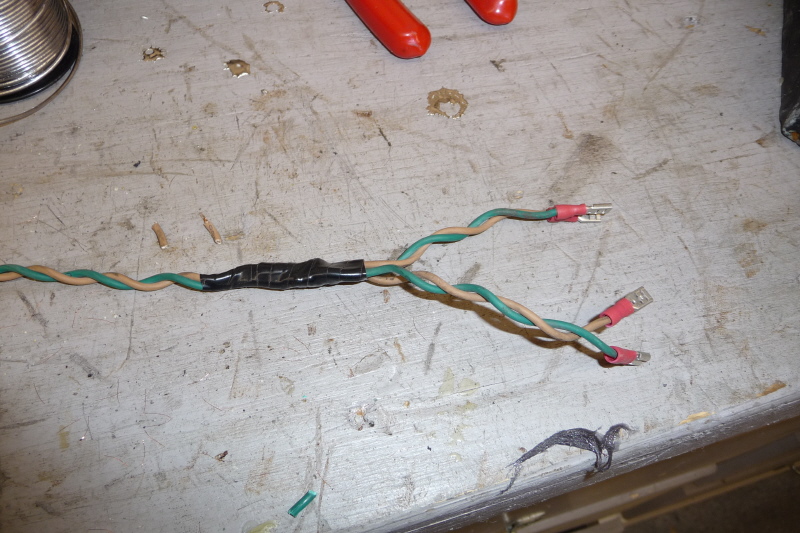
Another issue I have with the C3 is how the 12 gauge wire connects to the electronic module. I took flexible 12 gauge wire and crimped fork/spade terminals on the ends. Encased the three wires in shrink tube and routed it to the 2" x 4" utility box. Now when the electronic module is rotated forward, there is no stress on the circuit board by stiff romex wiring. |
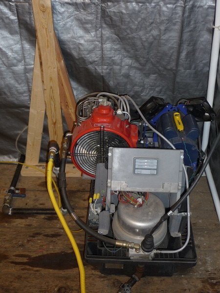
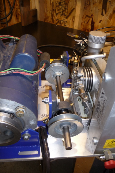
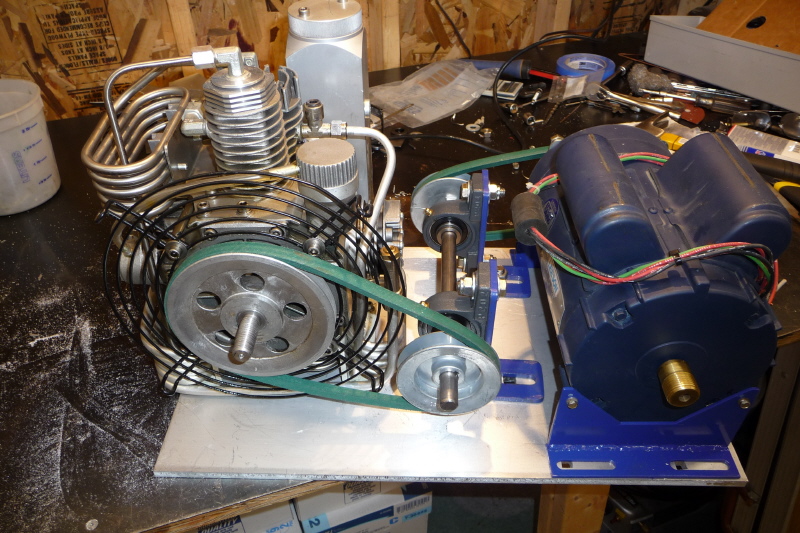
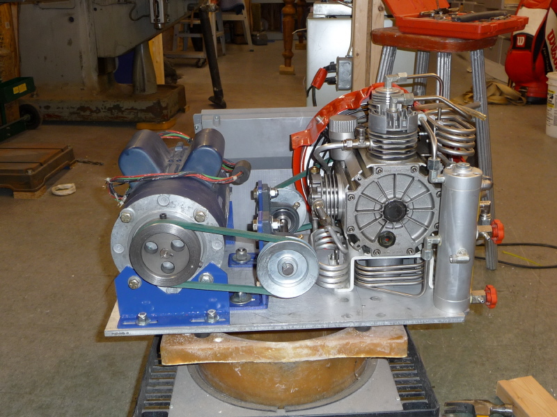
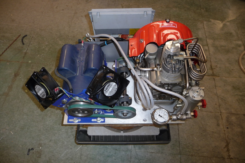
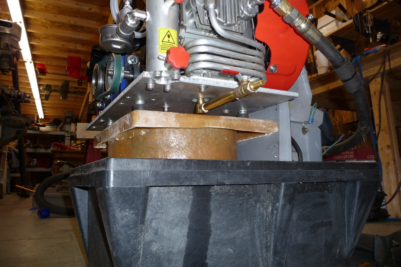
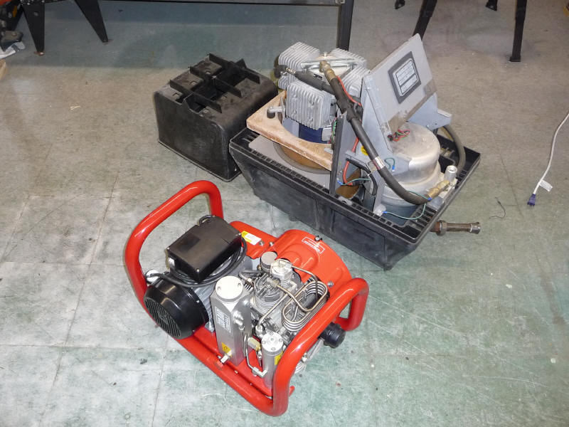
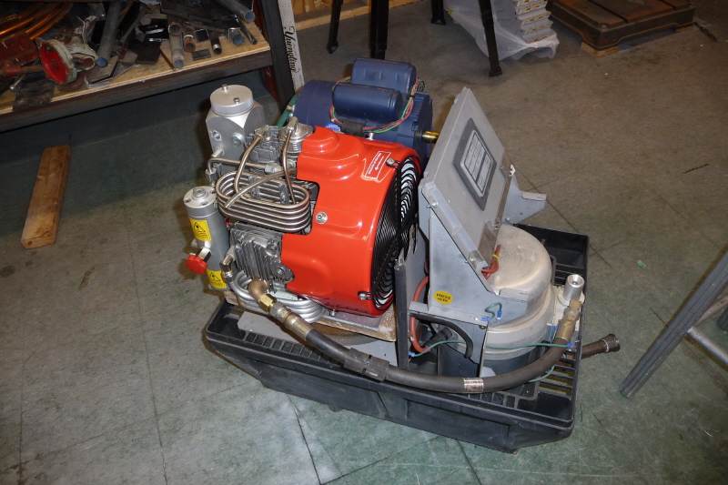
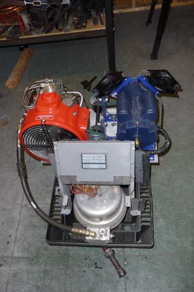
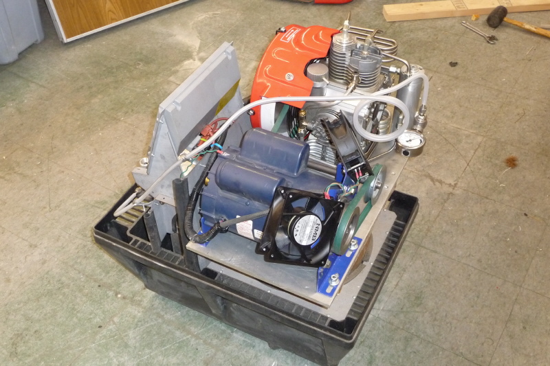
Here is a pic of the project setup for testing. I was disappointed with the performance of the unit. It must have lost volumetric efficiency when I reduced the RPM. So I changed out the pulleys on the jackshaft. One 1/2" smaller and the other 1/2" bigger. This increased the RPM of the compressor and units output. |

Here is another pic of the testing area. One of the first things I noticed was the three water/oil separators work so well that I removed my gas pre-heater and two deliquescent natural gas dryers and have moisture free gas. If I only knew about this years ago, I could have saved myself a ton on money and time experimenting with drying natural gas. |
In conclusion this has been a fun project. It has taken about 40 days of working in the evenings and around other projects to complete. I am very satisfied with the knowledge I have gained from this adventure. |
This site was created by Brian McKay 2004-2010, All Rights Reserved. Brian.McKay@littlemetalshop.com